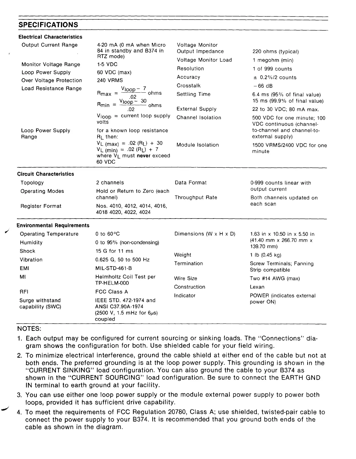
SPECIFICATIONS
Electrical Characteristics
Output Current Range
Monitor Voltage Range
Loop Power Supply
Over Voltage Protection
Load Resistance Range
4-20 mA (0 mA when Micro
84 in standby and B374 in
RTZ mode)
l-5 VDC
60 VDC (max)
240 VRMS
Vloop- 7
Rmax = nr,
ohms
J
Loop Power Supply
Range
.“L
Rmin =
Vloop- 30 ohms
.02
Vtoop = current loop supply
volts
for a known loop resistance
RL then:
VL (max) = .02 (RL) + 30
VL (min) = .02 (RL) + 7
where VL must never exceed
60 VDC
Voltage Monitor
Output Impedance
Voltage Monitor Load
Resolution
Accuracy
Crosstalk
Settling Time
External Supply
Channel Isolation
Module Isolation
220 ohms (typical)
1 megohm (min)
1 of 999 counts
f 0.2%12 counts
-66 dB
6.4 ms (95% of final value)
1.5 ms (99.9% of final value)
22 to 30 VDC; 80 mA max.
500 VDC for one minute; 100
VDC continuous (channel-
to-channel and channel-to-
external supply)
1500 VRMSI2400 VDC for one
minute
Circuit Characteristics
Topology
Operating Modes
Register Format
2 channels
Data Format
O-999 counts linear with
Hold or Return to Zero (each
output current
channel)
Throughput Rate
Both channels updated on
Nos. 4010, 4012, 4014, 4016,
each scan
4018 4020, 4022, 4024
Environmental Requirements
Operating Temperature
Humidity
Shock
Vibration
EMI
MI
RFI
Surge withstand
capability (SWC)
0 to 60°C
0 to 95% (non-condensing)
15 G for 11 ms
0.625 G, 50 to 500 Hz
MIL-STD-461-B
Helmholtz Coil Test per
TP-H ELM-000
FCC Class A
IEEE STD. 472-1974 and
ANSI C37.90A-1974
(2500 V, 1.5 mHz for 6~s)
couoled
Dimensions (W x H x D)
Weight
Termination
Wire Size
Construction
Indicator
1.63 in x 10.50 in x 5.50 in
(41.40 mm x 266.70 mm x
139.70 mm)
1 lb (0.45 kg)
Screw Terminals; Fanning
Strip compatible
Two #14 AWG (max)
Lexan
POWER (indicates external
power ON)
NOTES:
1. Each output may be configured for current sourcing or sinking loads. The “Connections” dia-
gram shows the configuration for both. Use shielded cable for your field wiring.
2. To minimize electrical interference, ground the cable shield at either end of the cable but not at
both ends. The preferred grounding is at the loop power supply. This grounding is shown in the
“CURRENT SINKING” load configuration. You can also ground the cable to your B374 as
shown in the “CURRENT SOURCING” load configuration. Be sure to connect the EARTH GND
IN terminal to earth ground at your facility.
3. You can use either one loop power supply or the module external power supply to power both
loops, provided it has sufficient drive capability.
4. To meet the requirements of FCC Regulation 20780, Class A; use shielded, twisted-pair cable to
connect the power supply to your B374. It is recommended that you ground both ends of the
cable as shown in the diagram.
Artisan Technology Group - Quality Instrumentation ... Guaranteed | (888) 88-SOURCE | www.artisantg.com