AC Power
DC Power
J
J
r
VOLT
sLcLT
GRND
AC
IN
NEUT
NO
CONNECTION
CON:E%TlON
GROUND
-DC IN
+DC IN
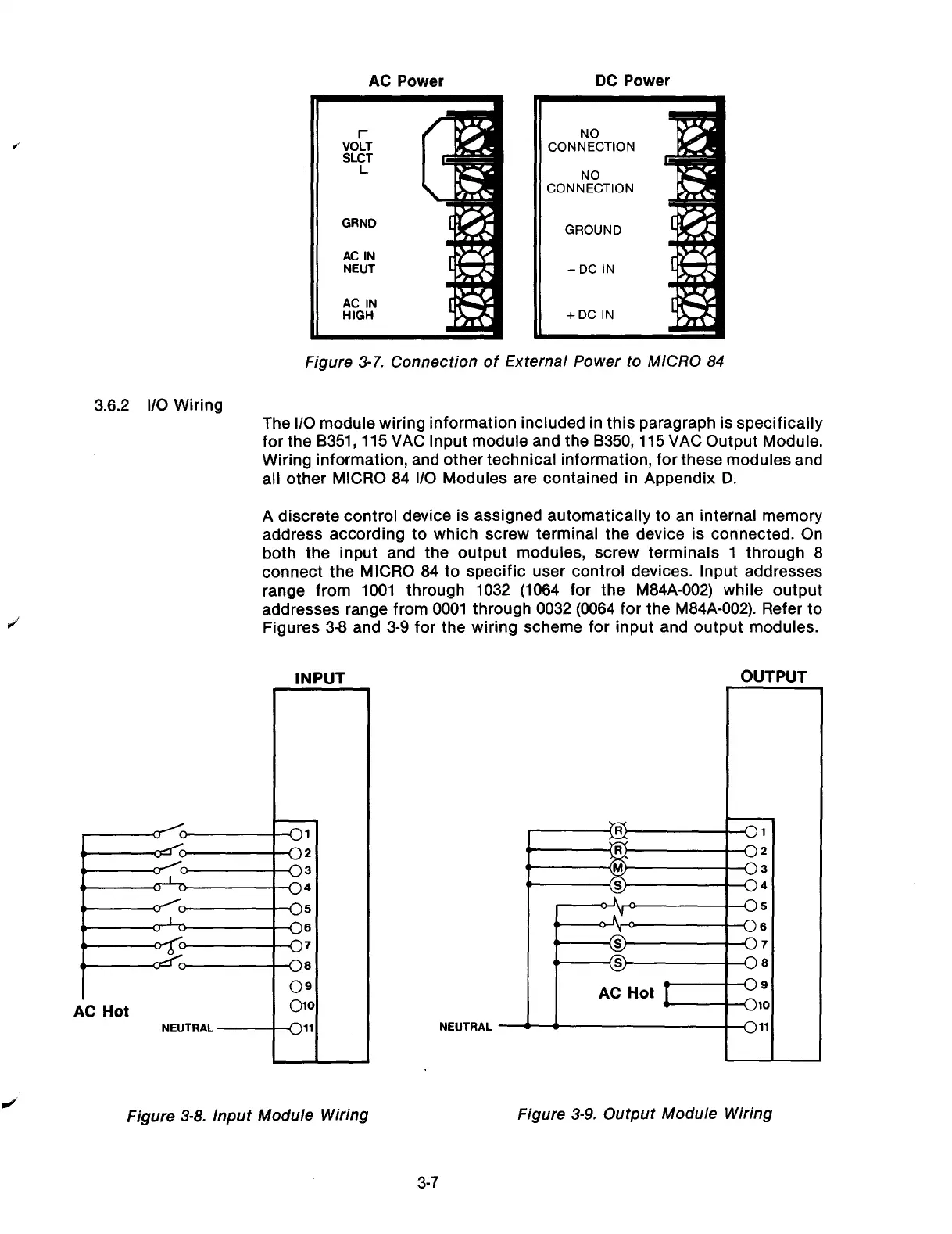
Figure 3-7. Connection of External Power to MICRO 84
3.6.2 l/O Wiring
The l/O module wiring information included in this paragraph is specifically
for the B351,115 VAC Input module and the 8350,115 VAC Output Module.
Wiring information, and other technical information, for these modules and
all other MICRO 84 l/O Modules are contained in Appendix D.
A discrete control device is assigned automatically to an internal memory
address according to which screw terminal the device is connected. On
both the input and the output modules, screw terminals 1 through 8
connect the MICRO 84 to specific user control devices. Input addresses
range from 1001 through
1032 (1064 for the M84A-002) while output
addresses range from 0001
through 0032 (0064 for the M84A-002). Refer to
Figures 38 and 3-9 for the
wiring scheme for input and output modules.
INPUT
OUTPUT
1
r
i
I;C
Hot
NEUTRAL
1
NEUTRAL -
AC
Hot [I;
-11
I
Figure 3-8. Input Module Wiring
Figure 3-9. Output Module Wiring
3-7
Artisan Technology Group - Quality Instrumentation ... Guaranteed | (888) 88-SOURCE | www.artisantg.com