SECTION 2
SYSTEM CONFIGURATION
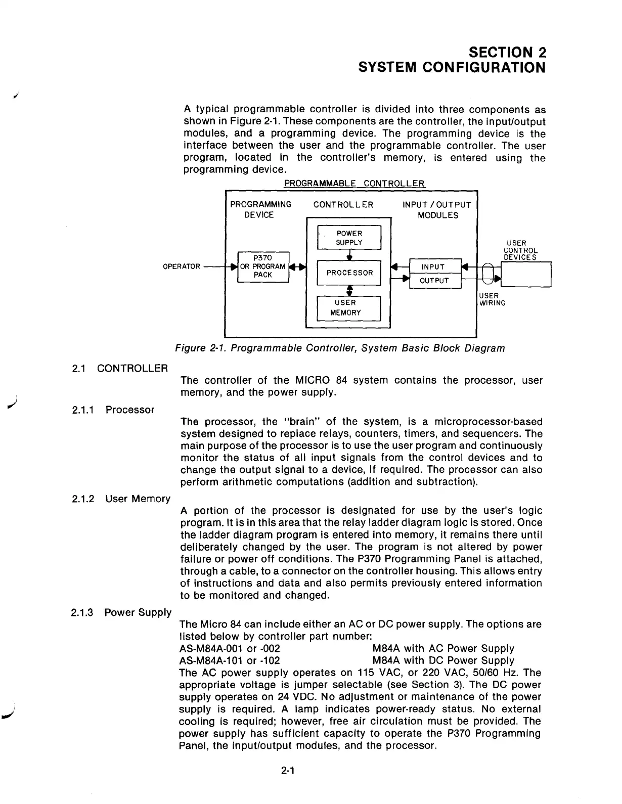
A typical programmable controller is divided into three components as
shown in Figure 2-1. These components are the controller, the input/output
modules, and a programming device. The programming device is the
interface between the user and the programmable controller. The user
program, located in the controller’s memory, is entered using the
programming device.
OPERATOR -
2.1 CONTROLLER
2.1.1 Processor
2.1.2 User Memory
2.1.3 Power Supply
PROGRAMMABLE CONTROLLER
PROGRAMMING
DEVICE
I
CONTROLLER
PROCESSOR
INPUT /OUTPUT
1
MODULES
INPUT
OUTPUT
i”
USER
CONTROL
DEVICES
ISER
YIRING
Figure 2-1. Programmable Controller, System Basic Block Diagram
The controller of the MICRO 84 system contains the processor, user
memory, and the power supply.
The processor, the “brain” of the system, is a microprocessor-based
system designed to replace relays, counters, timers, and sequencers. The
main purpose of the processor is to use the user program and continuously
monitor the status of all input signals from the control devices and to
change the output signal to a device, if required. The processor can also
perform arithmetic computations (addition and subtraction).
A portion of the processor is designated for use by the user’s logic
program. it is in this area that the relay ladder diagram logic is stored. Once
the ladder diagram program is entered into memory, it remains there until
deliberately changed by the user. The program is not altered by power
failure or power off conditions. The P370 Programming Panel is attached,
through a cable, to a connector on the controller housing. This allows entry
of instructions and data and also permits previously entered information
to be monitored and changed.
The Micro 84 can include either an AC or DC power supply. The options are
listed below by controller part number:
AS-M84A-001 or -002
M84A with AC Power Supply
AS-M84A-101 or -102
M84A with DC Power Supply
The AC power supply operates on 115 VAC, or 220 VAC, 50160 Hz. The
appropriate voltage is jumper selectable (see Section 3). The DC power
supply operates on 24 VDC. No adjustment or maintenance of the power
supply is required. A lamp indicates power-ready status. No external
cooling is required; however, free air circulation must be provided. The
power supply has sufficient capacity to operate the P370 Programming
Panel, the input/output modules, and the processor.
2-l
Artisan Technology Group - Quality Instrumentation ... Guaranteed | (888) 88-SOURCE | www.artisantg.com