SECTION 7
PROGRAMMING THE MICRO 84
J
The basic element used in programming the MICRO 84 Programmable
Controller is the contact. A contact can be either normally open or normally
closed. Associated with each contact is a logic element (indicating
whether the contact is normally open or normally closed) and a reference
number. The reference number ties the logic element to a specific
connection on the l/O input module. The input used to control the status
of a contact is called a discrete input (i.e., it turns the contact either to the
non-normal condition or returns it to the normal condition).
Another type of input that can be used is numeric data. This information
is stored in an input register. Each register also has an associated
reference number.
A coil is another logic element and its state (energized or de-energized) is
determined by the various inputs that control it. A coil is an output used
to control a specific piece of user equipment or as input to another
network. Each coil is associated with a specific reference number.
7.1 NETWORKS
In the MICRO 84, each program element occupies one or two “nodes”. The
nodes are arranged so that seven elements can be entered horizontally (a
rung on the ladder). Up to four rungs can be combined to form a network.
A network then, is the ladder diagram program. The number of logic
elements that can be contained in a MICRO 84 depends upon the
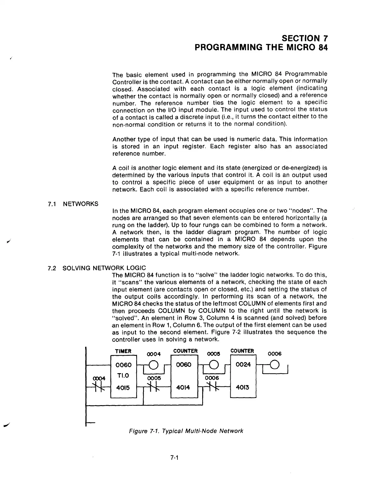
complexity of the networks and the memory size of the controller. Figure
7-1 illustrates a typical multi-node network.
7.2 SOLVING NETWORK LOGIC
The MICRO 84 function is to “solve” the ladder logic networks. To do this,
it “scans” the various elements of a network, checking the state of each
input element (are contacts open or closed, etc.) and setting the status of
the output coils accordingly. In performing its scan of a network, the
MICRO 84 checks the status of the leftmost COLUMN of elements first and
then proceeds COLUMN by COLUMN to the right until the network is
“solved”. An element in Row 3, Column 4 is scanned (and solved) before
an element in Row 1, Column 6. The output of the first element can be used
as input to the second element. Figure 7-2 illustrates the sequence the
controller uses in solving a network.
TIMER
0004
COUNTER
ooo5
COUNTER
0006
0060
0060
0024
TI.0
I
0005
0006
4015
-f-1_
4014
4013
Figure
7-l.
Typical Multi-Node Network
7-1
Artisan Technology Group - Quality Instrumentation ... Guaranteed | (888) 88-SOURCE | www.artisantg.com