3.5 COMPONENT MOUNTING
The MICRO 84 controller (M84A) unit is secured to the mounting surface
using two screws, one top and one bottom. See Figure 3-l. After securing
the controller unit, the first input/output module is plugged into the
controller using the connector located on the right side of the controller
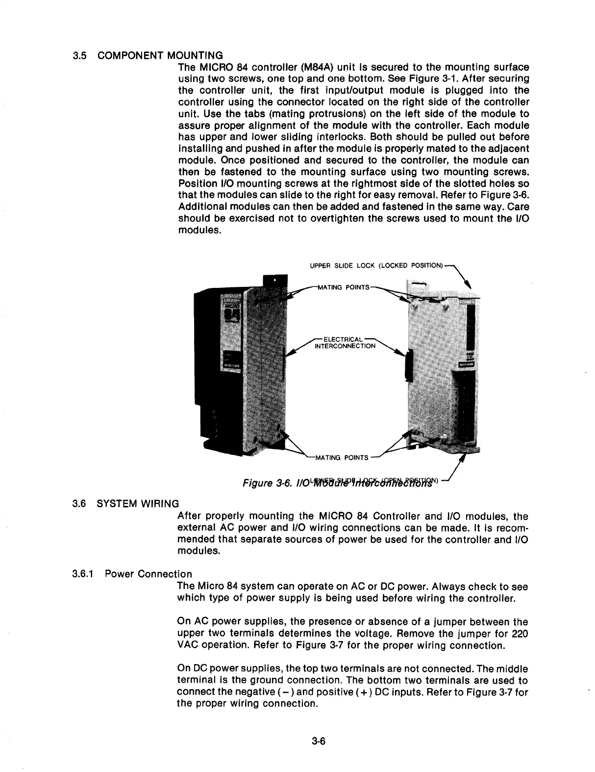
unit. Use the tabs (mating protrusions) on the left side of the module to
assure proper alignment of the module with the controller. Each module
has upper and lower sliding interlocks. Both should be pulled out before
installing and pushed in after the module is properly mated to the adjacent
module. Once positioned and secured to the controller, the module can
then be fastened to the mounting surface using two mounting screws.
Position l/O mounting screws at the rightmost side of the slotted holes so
that the modules can slide to the right for easy removal. Refer to Figure 3-8.
Additional modules can then be added and fastened in the same way. Care
should be exercised not to overtighten the screws used to mount the I/O
modules.
UPPER SLIDE LOCK (LOCKED POSITION)-,
--MATING POINTS
-ELECTRICAL
-MATING POINTS -
3.6 SYSTEM WIRING
After properly mounting the MICRO 84 Controller and l/O modules, the
external AC power and l/O wiring connections can be made. It is recom-
mended that separate sources of power be used for the controller and l/O
modules.
3.6.1 Power Connection
The Micro 84 system can operate on AC or DC power. Always check to see
which type of power supply is being used before wiring the controller.
On AC power supplies, the presence or absence of a jumper between the
upper two terminals determines the voltage. Remove the jumper for 220
VAC operation. Refer to Figure 3-7 for the proper wiring connection.
On DC power supplies, the top two terminals are not connected. The middle
terminal is the ground connection. The bottom two terminals are used to
connect the negative
(-)
and positive
(+)
DC inputs. Refer to Figure 3-7 for
the proper wiring connection.
3-6
Artisan Technology Group - Quality Instrumentation ... Guaranteed | (888) 88-SOURCE | www.artisantg.com