4
The new register contents appear in the DATA display. Enter the contents
into the register by pressing the SHIFT and ENTER keys sequentially.
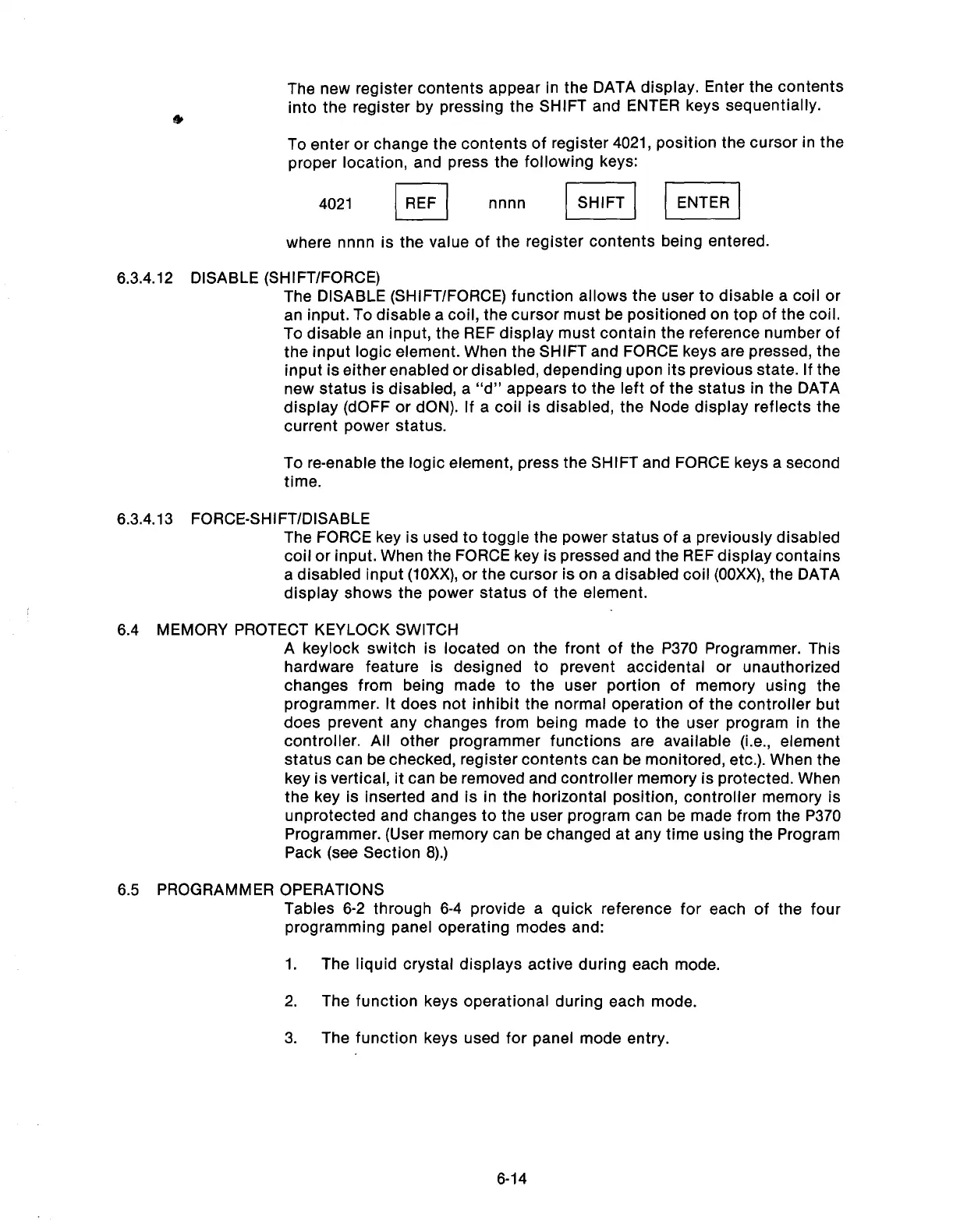
To enter or change the contents of register 4021, position the cursor in the
proper location, and press the following keys:
4021
I
FIEF
nnnn II /I
where nnnn is the value of the register contents being entered.
6.3.4.12 DISABLE (SHIFT/FORCE)
The DISABLE (SHIFT/FORCE) function allows the user to disable a coil or
an input. To disable a coil, the cursor must be positioned on top of the coil.
To disable an input, the REF display must contain the reference number of
the input logic element. When the SHIFT and FORCE keys are pressed, the
input is either enabled or disabled, depending upon its previous state. If the
new status is disabled, a “d” appears to the left of the status in the DATA
display (dOFF or dON). If a coil is disabled, the Node display reflects the
current power status.
To re-enable the logic element, press the SHIFT and FORCE keys a second
time.
6.3.4.13 FORCE-SHIFT/DISABLE
The FORCE key is used to toggle the power status of a previously disabled
coil or input. When the FORCE key is pressed and the REF display contains
a disabled input (10Xx), or the cursor is on a disabled coil (OOXX), the DATA
display shows the power status of the element.
6.4 MEMORY PROTECT KEYLOCK SWITCH
6.5 PROGRAMMER
OPERATIONS
A keylock switch is located on the front of the P370 Programmer. This
hardware feature is designed to prevent accidental or unauthorized
changes from being made to the user portion of memory using the
programmer. It does not inhibit the normal operation of the controller but
does prevent any changes from being made to the user program in the
controller. All other programmer functions are available (i.e., element
status can be checked, register contents can be monitored, etc.). When the
key is vertical, it can be removed and controller memory is protected. When
the key is inserted and is in the horizontal position, controller memory is
unprotected and changes to the user program can be made from the P370
Programmer. (User memory can be changed at any time using the Program
Pack (see Section 8).)
Tables 6-2 through 6-4 provide a quick reference for each of the four
programming panel operating modes and:
1.
The liquid crystal displays active during each mode.
2. The function keys operational during each mode.
3.
The function keys used for panel mode entry.
6-14
Artisan Technology Group - Quality Instrumentation ... Guaranteed | (888) 88-SOURCE | www.artisantg.com