A female socket is located on the right side of the controller housing. This
socket is the link between the controller unit and the input/output and
register modules. A terminator plug, supplied with the controller, must be
inserted into the rightmost I/O module during system operation. Programs
can be generated in the MICRO-84 without any I/O modules as long as the
terminator plug is inserted into this socket.
3.4 INPUT/OUTPUT MODULES
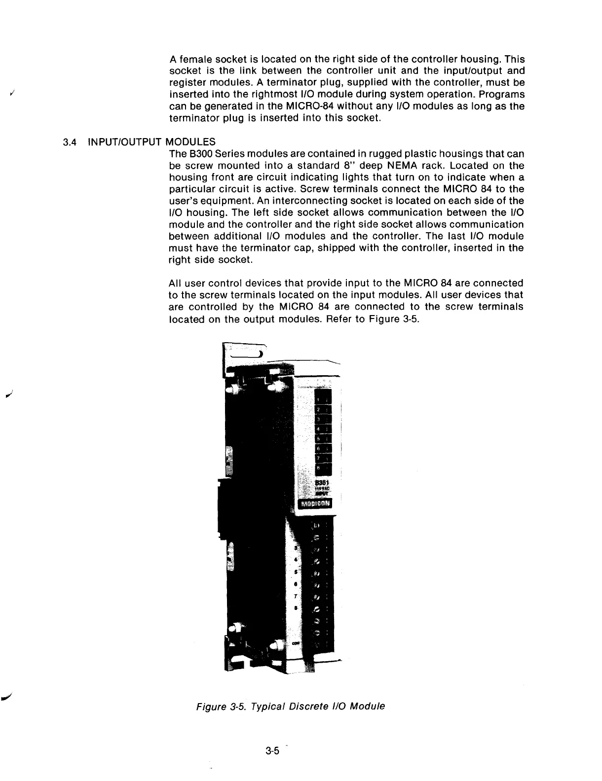
The B300 Series modules are contained in rugged plastic housings that can
be screw mounted into a standard 8” deep NEMA rack. Located on the
housing front are circuit indicating lights that turn on to indicate when a
particular circuit is active. Screw terminals connect the MICRO 84 to the
user’s equipment. An interconnecting socket is located on each side of the
l/O housing. The left side socket allows communication between the l/O
module and the controller and the right side socket allows communication
between additional I/O modules and the controller. The last I/O module
must have the terminator cap, shipped with the controller, inserted in the
right side socket.
All user control devices that provide input to the MICRO 84 are connected
to the screw terminals located on the input modules. All user devices that
are controlled by the MICRO 84 are connected to the screw terminals
located on the output modules. Refer to Figure 3-5.
J
Figure 3-5. Typical Discrete I/O Module
3-5
-
Artisan Technology Group - Quality Instrumentation ... Guaranteed | (888) 88-SOURCE | www.artisantg.com