SECTION 3
SYSTEM INSTALLATION
i
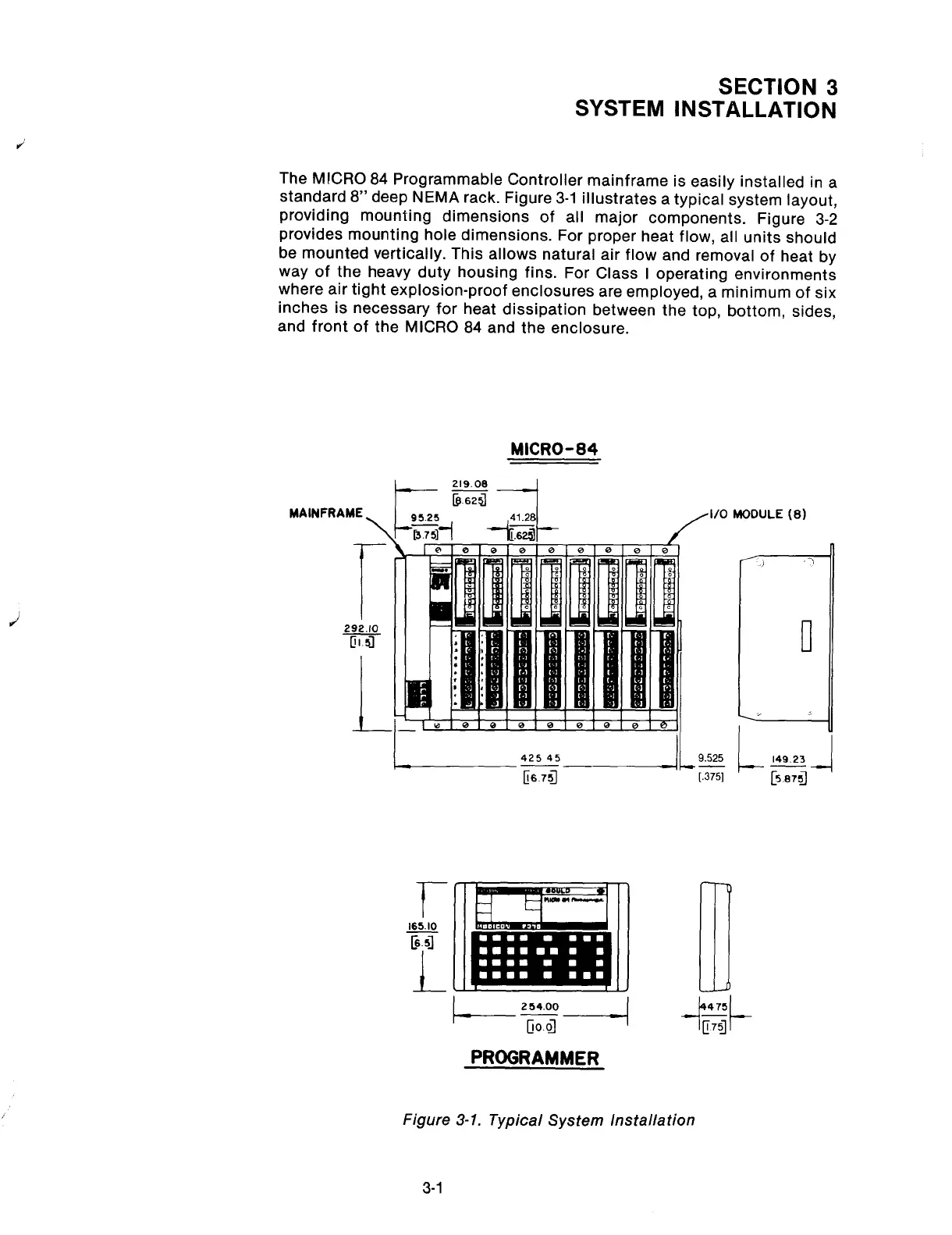
The MICRO 84 Programmable Controller mainframe is easily installed in a
standard 8” deep NEMA rack. Figure 3-1 illustrates a typical system layout,
providing mounting dimensions of all major components. Figure 3-2
provides mounting hole dimensions. For proper heat flow, all units should
be mounted vertically. This allows natural air flow and removal of heat by
way of the heavy duty housing fins. For Class I operating environments
where air tight explosion-proof enclosures are employed, a minimum of six
inches is necessary for heat dissipation between the top, bottom, sides,
and front of the MICRO 84 and the enclosure.
MICRO-84
MAINFRAME
7=’
PROGRAMMER
Figure 3-1. Typical System Installation
3-1
Artisan Technology Group - Quality Instrumentation ... Guaranteed | (888) 88-SOURCE | www.artisantg.com