6.1.1 Examine Mode
l
Normal monitoring of network power flow and status of any node within
the network.
l
Monitoring the value or status of any register or coil (using the REF key)
that is not associated with the node located at the cursor position.
l
In the HOLD state, the contents of the Data display are frozen, allowing
examination of the reference value.
The programming panel enters the EXAMINE mode automatically after the
power up diagnostics have successfully completed. The cursor is
positioned at row 1, column 1 of network 1.
6.1.2 Enter Mode
In the Enter mode, new information is entered into the programmer for
subsequent entry into the controller. This can be new nodes, updating
existing node information (reference, element type), register values, etc.
6.1.3 Supervisory Mode
6.1.4 Error Mode
6.2 DISPLAY AREA
The Supervisory mode allows the user to enter and initiate the supervisory
commands for the controller’s internal memory.
In the event of a programmer or controller error condition (diagnostic error,
communication error, or user error in entering data), the programmer
automatically enters the error mode and displays the appropriate error
code.
Depending on the error code present, certain keys will be operational. The
RESET key or the SHIFT/RESET keys are used to recover from an error
condition (see Appendix A).
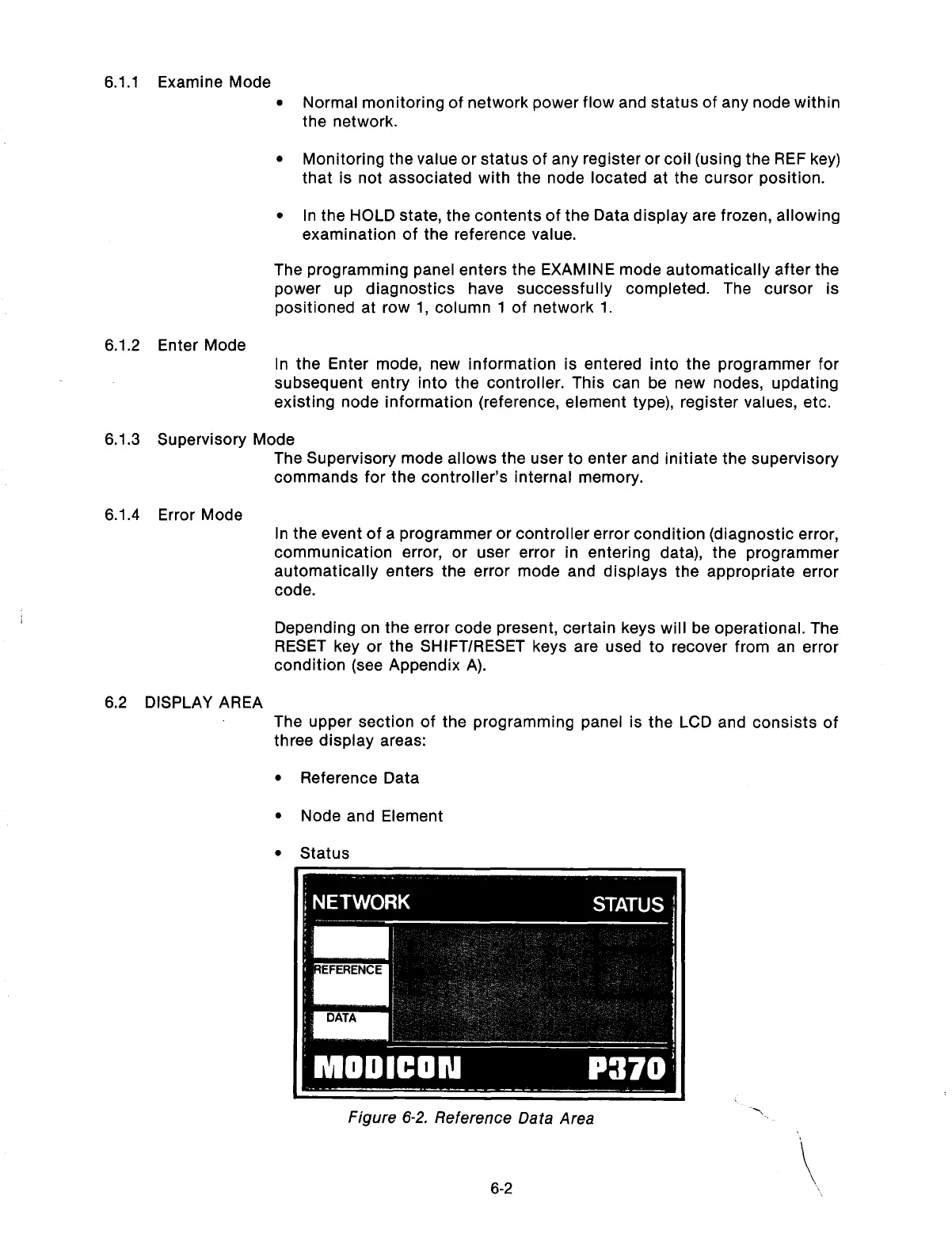
The upper section of the programming panel is the LCD and consists of
three display areas:
l
Reference Data
l
Node and Element
l
Status
6-2
Artisan Technology Group - Quality Instrumentation ... Guaranteed | (888) 88-SOURCE | www.artisantg.com