J
d
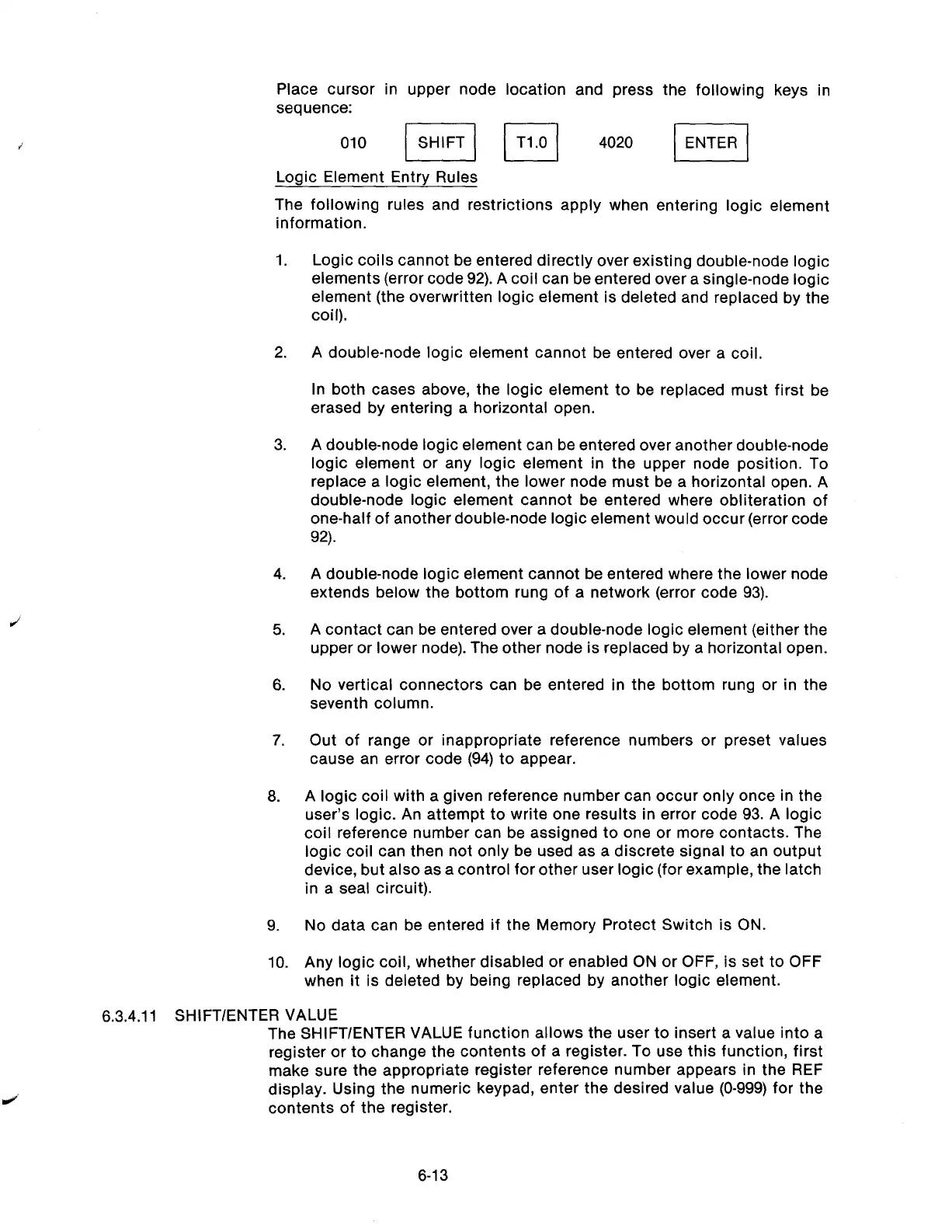
Place cursor in upper node location and press the following keys in
sequence:
010 jl lT1.01 4020 I]
Logic Element Entry Rules
The following rules and restrictions apply when entering logic element
information.
1.
Logic coils cannot be entered directly over existing double-node logic
elements (error code 92). A coil can be entered over a single-node logic
element (the overwritten logic element is deleted and replaced by the
coil).
2.
A double-node logic element cannot be entered over a coil.
In both cases above, the logic element to be replaced must first be
erased by entering a horizontal open.
3.
A double-node logic element can be entered over another double-node
logic element or any logic element in the upper node position. To
replace a logic element, the lower node must be a horizontal open. A
double-node logic element cannot be entered where obliteration of
one-half of another double-node logic element would occur (error code
92).
4.
A double-node logic element cannot be entered where the lower node
extends below the bottom rung of a network (error code 93).
5.
A contact can be entered over a double-node logic element (either the
upper or lower node). The other node is replaced by a horizontal open.
6.
No vertical connectors can be entered in the bottom rung or in the
seventh column.
7.
6.
9.
10.
Out of range or inappropriate reference numbers or preset values
cause an error code (94) to appear.
A logic coil with a given reference number can occur only once in the
user’s logic. An attempt to write one results in error code 93. A logic
coil reference number can be assigned to one or more contacts. The
logic coil can then not only be used as a discrete signal to an output
device, but also as a control for other user logic (for example, the latch
in a seal circuit).
No data can be entered if the Memory Protect Switch is ON.
Any logic coil, whether disabled or enabled ON or OFF, is set to OFF
when it is deleted by being replaced by another logic element.
6.3.4.11 SHIFT/ENTER VALUE
The SHIFT/ENTER VALUE function allows the user to insert a value into a
register or to change the contents of a register. To use this function, first
make sure the appropriate register reference number appears in the REF
display. Using the numeric keypad, enter the desired value (O-999) for the
contents of the register.
6-13
Artisan Technology Group - Quality Instrumentation ... Guaranteed | (888) 88-SOURCE | www.artisantg.com