position. For single node functions the initial or altered information can be
the reference number, element type, and vertical or horizontal connectors.
For double-node functions, entry of initial information involves both the
upper and lower nodes; changing existing information may involve only the
upper or the lower node or both nodes.
Entering a Single-Node Logic Element
Any combination of allowable numeric values (reference numbers, preset
values, etc.) and logic elements (contacts, coils, timers, etc.) can be
entered for a single-node logic element. As soon as any numeric or element
key is pressed, the controller goes into the ENTER mode. The last value
entered for either the numeric value or logic element prior to pressing the
ENTER key is the one that is valid and is entered into the controller (for
example, after entering a normally closed contact, the user can have a
change of mind and enter a normally open contact). There is no preferred
sequence for entering numeric values and logic elements. When all the
information is correct, press the ENTER key.
For example, to enter a normally closed contact with reference number
1017, place the cursor in the proper location, and press the following keys:
1017 p/ II
The same sequence is required when changing the logic element (i.e., the
reference number must be specified even if it is not changing).
Entering a Double-Node Logic Element
Double-node logic elements are characterized by numeric values that must
be entered into both the upper and lower nodes. The upper node contains
a preset value (O-999) or the reference number of the register that contains
the preset value (300X or 40Xx). The lower node contains the reference
number of the holding register (40Xx). Double-node logic elements must be
entered in specific sequence. If this sequence is not followed, an error
code will be displayed.
1.
2.
3.
4.
5.
Position the cursor at the location of the top half of the double-node
logic element.
Enter the preset value. The preset value appears in the DATA display
area.
Enter the double-node logic element type (counter, T1.O, TO.l, + ,
-).
When this is entered, the preset value moves from the DATA display
area to the REFERENCE display area. The Element display area
contains the selected logic element.
Enter the reference number of the holding register (accumulated time,
accumulated count, or overflow). Vertical connections can be entered
also.
Press ENTER.
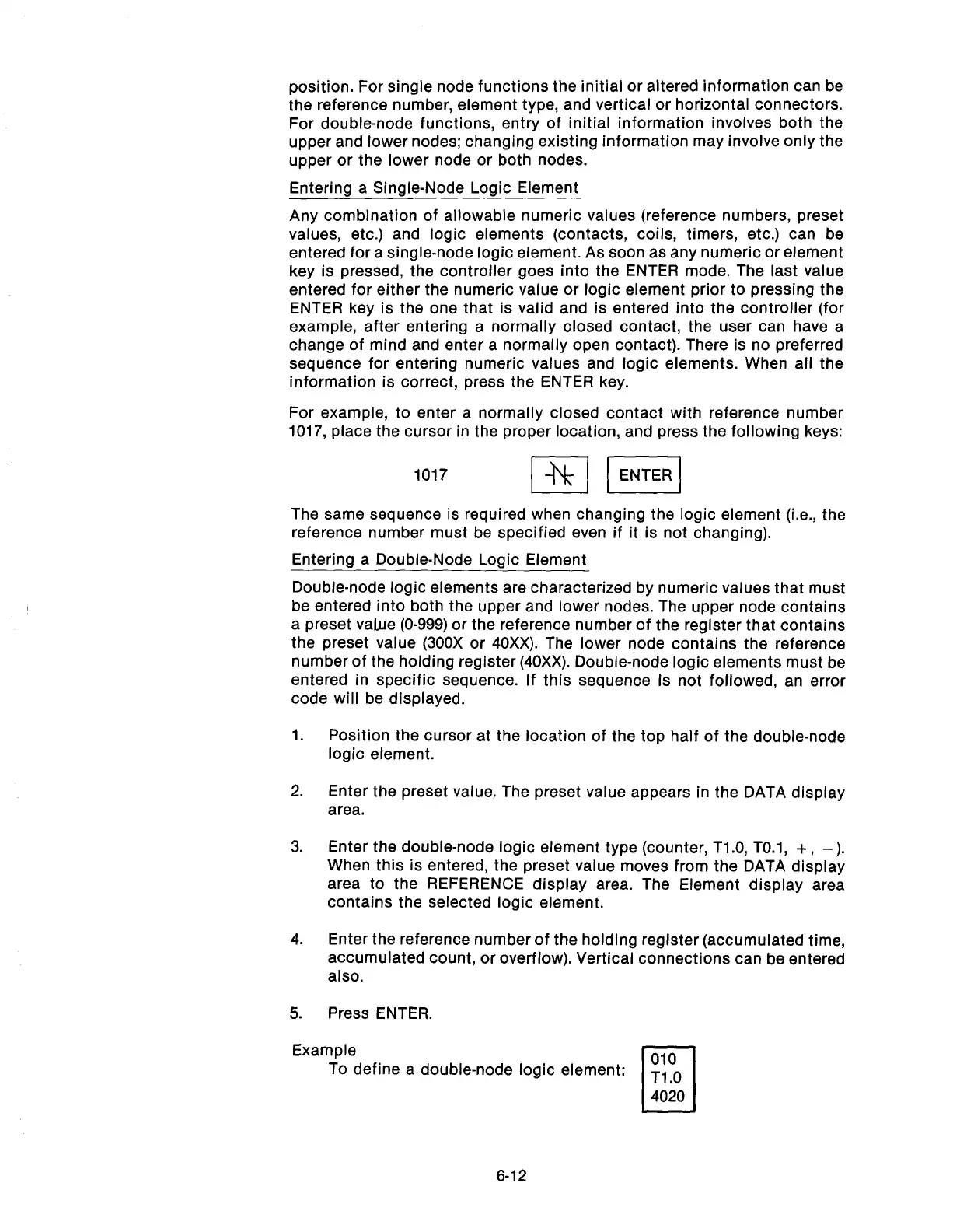
Example
To define a double-node logic element:
010
c
Tl .O
4020
6-12
Artisan Technology Group - Quality Instrumentation ... Guaranteed | (888) 88-SOURCE | www.artisantg.com