3.3 CONTROLLER
J
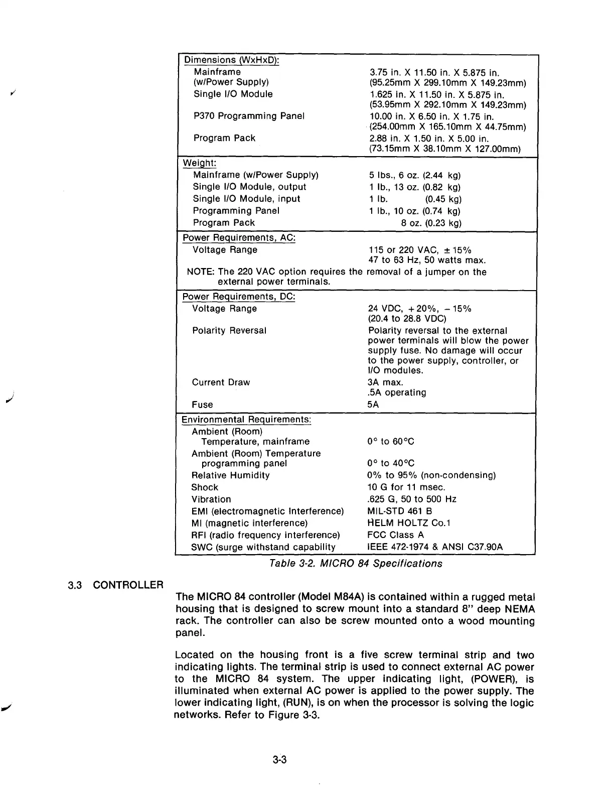
Dimensions (WxHxD):
Mainframe
(w/Power Supply)
Single l/O Module
P370 Programming Panel
Program Pack
3.75 in. X 11.50 in. X 5.875 in.
(95.25mm X 299.lOmm X 149.23mm)
1.625 in. X 11.50 in. X 5.875 in.
(53.95mm X 292.lOmm X 149.23mm)
10.00 in. X 6.50 in. X 1.75 in.
(254.00mm X 165.lOmm X 44.75mm)
2.88 in. X 1.50 in. X 5.00 in.
(73.15mm X 38.lOmm X 127.00mm)
Weight:
Mainframe (w/Power Supply)
5 Ibs., 6 oz. (2.44 kg)
Single l/O Module, output 1 lb., 13 oz. (0.82 kg)
Single l/O Module, input
1 lb. (0.45 kg)
Programming Panel
1 lb., 10 oz. (0.74 kg)
Program Pack
8 oz. (0.23 kg)
Power Requirements, AC:
Voltage Range
115 or 220 VAC, f 15%
47 to 63 Hz, 50 watts max.
NOTE: The 220 VAC option requires the removal of a jumper on the
external power terminals.
Power Requirements,
DC:
Voltage Range
24 VDC, + 20%, - 15%
(20.4 to 28.8 VDC)
Polarity Reversal
Polarity reversal to the external
power terminals will blow the power
supply fuse. No damage will occur
to the power supply, controller, or
I/O modules.
Current Draw
3A max.
.5A operating
Fuse
5A
Environmental Requirements:
Ambient (Room)
Temperature, mainframe
O” to 60°C
Ambient (Room) Temperature
programming panel
o” to 4o”c
Relative Humidity
0% to 95% (non-condensing)
Shock
10 G for 11 msec.
Vibration
.625 G, 50 to 500 Hz
EMI (electromagnetic Interference)
MIL-STD 461 6
Ml (magnetic interference)
HELM HOLTZ Co.1
RFI (radio frequency interference)
FCC Class A
SWC (surge withstand capability
IEEE 472-1974 & ANSI C37.90A
Table 3-2. MICRO 84 Specifications
The
MICRO 84 controller (Model M84A) is contained within a rugged metal
housing that is designed to screw mount into a standard 8” deep NEMA
rack. The controller can also be screw mounted onto a wood mounting
panel.
Located on the housing front is a five screw terminal strip and two
indicating lights. The terminal strip is used to co.nnect external AC power
to the MICRO 84 system. The upper indicating light, (POWER), is
illuminated when external AC power is applied to the power supply. The
lower indicating light, (RUN), is on when the processor is solving the logic
networks. Refer to Figure 3-3.
3-3
Artisan Technology Group - Quality Instrumentation ... Guaranteed | (888) 88-SOURCE | www.artisantg.com