I 2 3 4 5 6 7
Figure 7-2. Network Solving Sequence
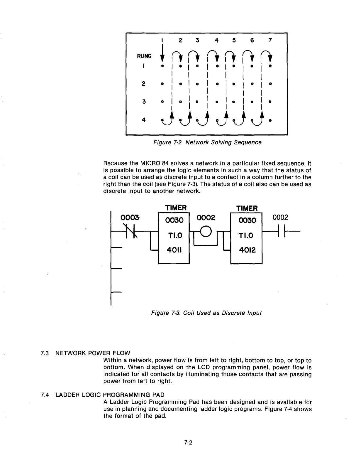
Because the MICRO 84 solves a network in a particular fixed sequence, it
is possible to arrange the logic elements in such a way that the status of
a coil can be used as discrete input to a contact in a column further to the
right than the coil (see Figure 7-3). The status of a coil also can be used as
discrete input to another network.
TIMER
TIMER
0003
0030
0002
r-l
0030
0002
I I__
TI.0
-
4011
I
1
Figure 7-3. Coil Used as Discrete Input
7.3 NETWORK POWER FLOW
Within a network, power flow is from left to right, bottom to top, or top to
bottom. When displayed on the LCD programming panel, power flow is
indicated for all contacts by illuminating those contacts that are passing
power from left to right.
7.4 LADDER LOGIC PROGRAMMING PAD
A Ladder Logic Programming Pad has been designed and is available for
use in planning and documenting ladder logic programs. Figure 7-4 shows
the format of the pad.
7-2
Artisan Technology Group - Quality Instrumentation ... Guaranteed | (888) 88-SOURCE | www.artisantg.com