SECTION 6
P370 PROGRAMMER
J
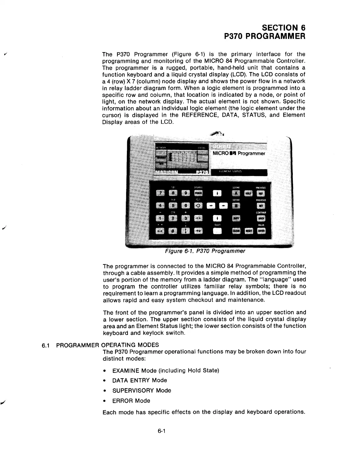
The P370 Programmer (Figure 6-1) is the primary interface for the
programming and monitoring of the MICRO 84 Programmable Controller.
The programmer is a rugged, portable, hand-held unit that contains a
function keyboard and a liquid crystal display (LCD). The LCD consists of
a 4 (row) X 7 (column) node display and shows the power flow in a network
in relay ladder diagram form. When a logic element is programmed into a
specific row and column, that location is indicated by a node, or point of
light, on the network display. The actual element is not shown. Specific
information about an individual logic element (the logic element under the
cursor) is displayed in the REFERENCE, DATA, STATUS, and Element
Display areas of the LCD.
The programmer is connected to the MICRO 84 Programmable Controller,
through a cable assembly. It provides a simple method of programming the
user’s portion of the memory from a ladder diagram. The “language” used
to program the controller utilizes familiar relay symbols; there is no
requirement to learn a programming language. In addition, the LCD readout
allows rapid and easy system checkout and maintenance.
The front of the programmer’s panel is divided into an upper section and
a lower section. The upper section consists of the liquid crystal display
area and an Element Status light; the lower section consists of the function
keyboard and keylock switch.
6.1 PROGRAMMER OPERATING MODES
The P370 Programmer operational functions may be broken down into four
distinct modes:
J
l
EXAMINE Mode (including Hold State)
l
DATA ENTRY Mode
l
SUPERVISORY Mode
l
ERROR Mode
Each mode has specific effects on the display and keyboard operations.
6-l
Artisan Technology Group - Quality Instrumentation ... Guaranteed | (888) 88-SOURCE | www.artisantg.com