6.3.4.3. SUPV
The register number assigned to the A and B keys can be changed to any
of the available registers (40Xx only) whose contents are viewed frequent-
ly. These new assignments will be in effect until changed (i.e., assign-
ments are not affected by power down).
To change the assigned register number, enter the desired register number
into the data display, then press SHIFT/A or SHIFT/B as appropriate. The
SHIFT is required to choose the DEFINE A or DEFINE B function. The
register number entered appears in the reference display and the register
contents appear in the data display. During this interval the element
display goes blank.
NOTE
The redefined A and B register assignments will not be
maintained when the user’s program logic is dumped to the
P371 Program Deck. When the logic is reloaded, the 4010
and 4020 assignments will be
in effect.
The supervisory mode can only be used if the Memory Protect feature is
OFF. It is entered by pressing the SUPV key. When in any mode other than
the supervisory mode, pressing the SUPV key causes the following
displays to blank: network, data, power flow and cursor, element type,
enter, examine, and element status light. The REFERENCE display reads
SUP0 for panel mode operation. COMM OK remains illuminated.
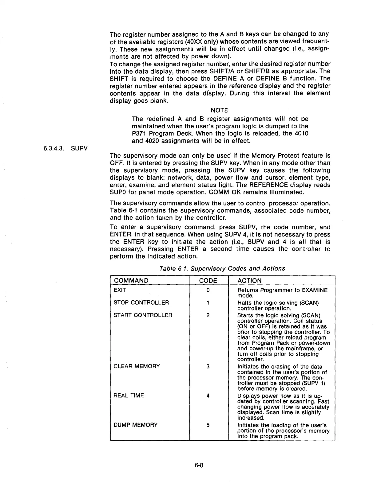
The supervisory commands allow the user to control processor operation.
Table 6-l contains the supervisory commands, associated code number,
and the action taken by the controller.
To enter a supervisory command, press SUPV, the code number, and
ENTER, in that sequence. When using SUPV 4, it is not necessary to press
the ENTER key to initiate the action (i.e., SUPV and 4 is all that is
necessary). Pressing ENTER a second time causes the controller to
perform the indicated action.
Table 6-1. Supervisory Codes and Actions
COMMAND
EXIT
STOP CONTROLLER
START CONTROLLER
CLEAR MEMORY
REAL TIME
DUMP MEMORY
CODE ACTION
0
Returns Programmer to EXAMINE
mode.
1 Halts the logic solving (SCAN)
controller operation.
2
Starts the logic solving (SCAN)
controller operation. Coil status
(ON or OFF) is retained as it was
prior to stopping the controller. To
clear coils, either reload program
from Program Pack or power-down
and power-up the mainframe, or
turn off coils prior to stopping
controller.
3
Initiates the erasing of the data
contained in the user’s portion of
the processor memory. The con-
troller must be stopped (SUPV 1)
before memory is cleared.
4
Displays power flow as it is up-
dated by controller scanning. Fast
changing power flow is accurately
displayed. Scan time is slightly
increased.
5
Initiates the loading of the user’s
portion of the processor’s memory
into the program pack.
6-8
Artisan Technology Group - Quality Instrumentation ... Guaranteed | (888) 88-SOURCE | www.artisantg.com