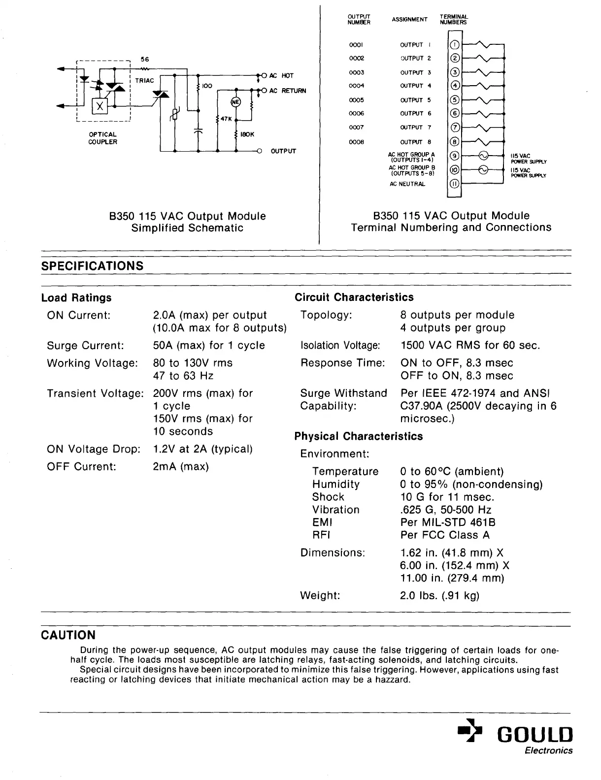
r______-_~ 56
AC HOT
AC RETURN
OPTICAL
COUPLER
.
IeOK
.
CJ OUTPUT
6350 115 VAC Output Module
Simplified Schematic
OUTPUT
NUMBER
ASSIGNMENT
TERMINAL
NUMBERS
/
0001
1
LIZ
0004
ooo5
0006
0037
0008
OUTPUT I
Ok
OUTPUT 2
o--+.r+
OUTPUT 3
o--b+
OUTPUT 4
@--2/--I
OUTPUT 5
OUTFUT 6
OUTPUT 7
o-+--t
OUTFWT 6
a+’
AC HOT GROUP A
(OUTPUFS l-4)
a---@--’ Ii5VAC
POWER SUPR’,
AC HOT GROUP 6
LOUTFIJTS 5-6!
B--Q+ 115vAC
PCWERSJPRY
AC NEUTRAL
0,
-
8350 115 VAC Output Module
Terminal Numbering and Connections
SPECIFICATIONS
Load Ratings
ON
Current:
Circuit Characteristics
2.OA (max) per output Topology:
8 outputs per module
(lO.OA max for 8 outputs)
4 outputs per group
Surge Current: 50A (max) for 1 cycle
Isolation Voltage:
1500 VAC RMS for 60 sec.
Working Voltage: 80 to 130V rms Response Time:
ON to OFF, 8.3 msec
47 to 63 Hz
OFF to ON, 8.3 msec
Transient Voltage: 200V rms (max) for Surge Withstand
Per IEEE 472-1974 and ANSI
1 cycle
Capability:
C37.90A (2500V decaying in 6
150V rms (max) for
microsec.)
10 seconds
Physical Characteristics
ON
Voltage Drop:
1.2V at 2A (typical)
Environment:
OFF Current: 2mA (max)
Temperature
0 to 60°C (ambient)
Humidity
0 to 95% (non-condensing)
Shock
10 G for 11 msec.
Vibration
.625 G, 50-500 Hz
EMI
Per MIL-STD 461 B
RFI
Per FCC Class A
Dimensions:
1.62 in. (41.8 mm) X
6.00 in. (152.4 mm) X
11.00 in. (279.4 mm)
Weight:
2.0 Ibs. (.91 kg)
CAUTION
During the power-up sequence, AC output modules may cause the false triggering of certain loads for one-
half cycle. The loads most susceptible are latching relays, fast-acting solenoids, and latching circuits.
Special circuit designs have been incorporated to minimize this false triggering. However, applications using fast
reacting or latching devices that initiate mechanical action may be a hazard.
1)1
GOULD
Artisan Technology Group - Quality Instrumentation ... Guaranteed | (888) 88-SOURCE | www.artisantg.com