06/05/13 AERCO International, Inc. • 100 Oritani Dr. • Blauvelt, NY 10913 • Ph: 800-526- 0288 Page 86 of 112
Modulex E8 Controller and BCM
Operations and Maintenance Manual
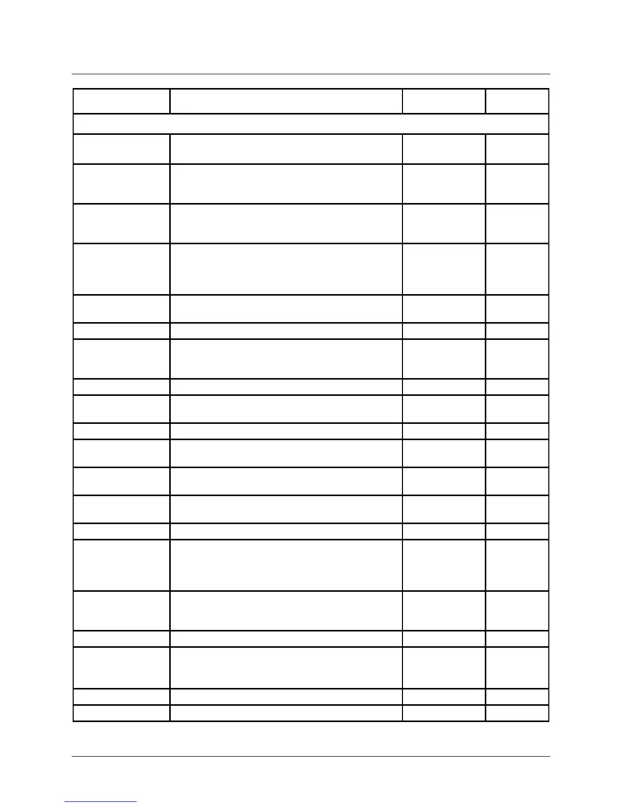
FUNCTION DESCRIPTION
DEFAULT
INSTALLATION Sub-Menu (Continued)
HYSTERESIS
Dynamic Switching hysteresis stage 1.
5K - 20K
(N/A)
5.0K
(N/A)
FOUND MODULS
Display of heat generators automatically
reported via BUS with BUS ID. Displays the
number of heat modules available for service.
display
CAP/MODULE
After restarting, the Controller, searches the bus
systems for available new heat modules and the
maximum kW output of each heat module.
00 - 1000 kW 40 kW
NEW CONFIG
If the BUS configuration was modified, the
automatic search for generators on the BUS may
be activated here.
(Currently Not Applicable)
00, 01
(OFF/ON)
(N/A)
00
(N/A)
MIN MOD CASC
Specifies the number of heat modules started
01 - 08 01
Number of stages for HW operation
CONTR DEVIAT
Control Deviation indicates the temperature
difference between the header set point and the
display F
Required system output [in %]
SWITCH TIME Internal control value: only for switching cascade (-99) - 0 - (99)
Display
MAX T-MODUL Maximum temperature of Heat Module
122.0°F –
194.0°F
DYN UPWARD
Dynamic heat generator connection
(N/A) (N/A)
DYN
Dynamic heat generator deactivation
(N/A) (N/A)
Resetting time for Controller (seconds)
MODULAT MAX
Start Level. If this modulation percentage is
exceeded, the next heat generator (module) is
connected after the delay time specified by the
SEQ SW TIME (see below) elapses.
50% - 100% 30%
MODULAT MIN
Stop Level. If value drops below this modulation
percentage, the last heat generator (module) of
the current sequence is switched off
10% - 60% 35%
Connection of the next heat generator
MOD LEVEL HW
Entry of the set modulation percentage for the
heat generators in hot water operation
(Currently Not Applicable)
40% - 100%
(N/A)
80%
(N/A)
Table 8-4: EXPERT Menu Sub-Menus and Parameters (Continued)