06/05/13 AERCO International, Inc. • 100 Oritani Dr. • Blauvelt, NY 10913 • Ph: 800-526- 0288 Page 87 of 112
Modulex E8 Controller and BCM
Operations and Maintenance Manual
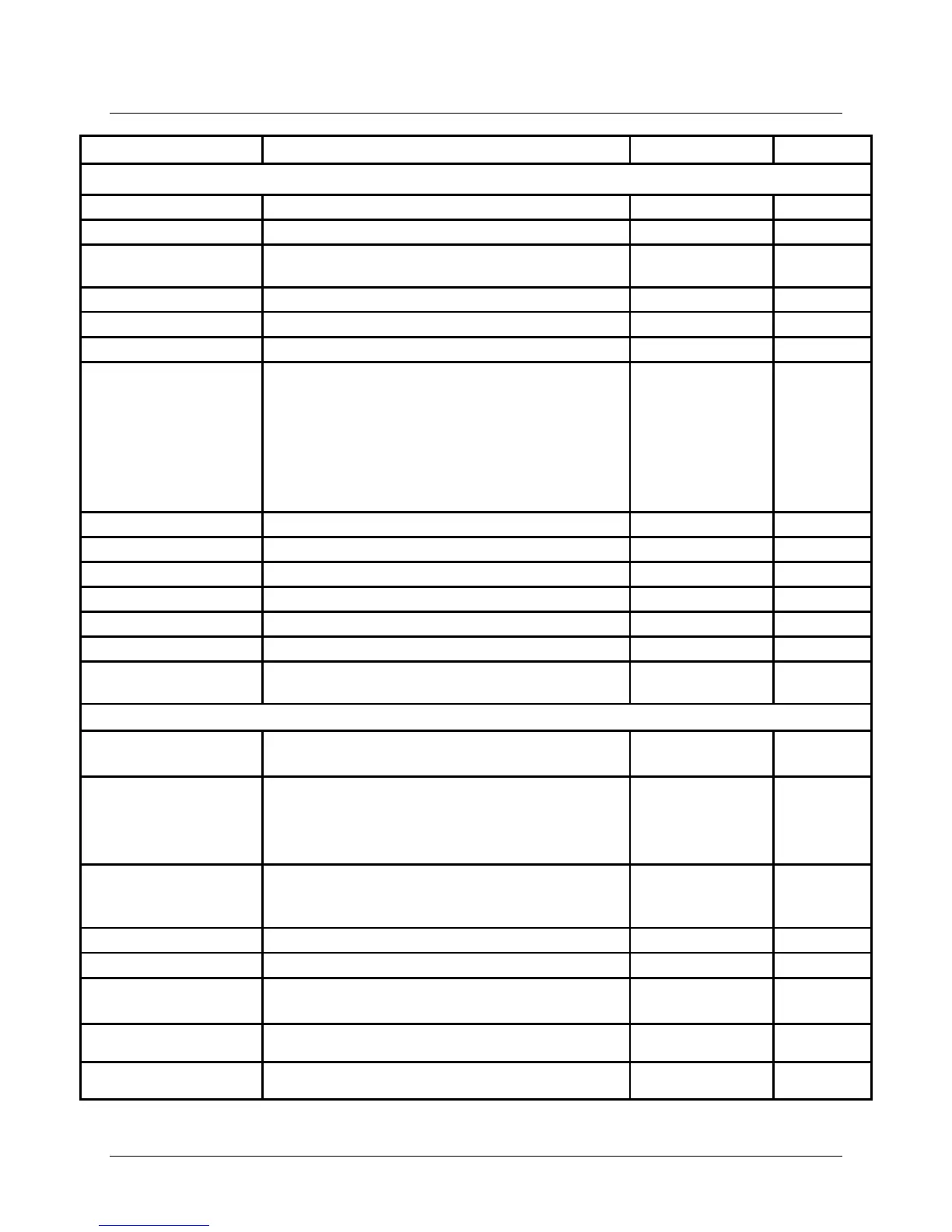
ENTRY RANGE
INSTALLATION Sub-Menu (Continued)
Time to sequence change (seconds)
LOCK TIME
Min. delay time after switching ON or with
00 min - 30 min 00
Solid fuel integration: hysteresiys for charging pump
HEATSOURCE 1
Identification of Boiler Type being used:
00 = No Boiler
01 = Single-Stage, switching
02 = Single-Stage, modulating
03 = 2-Stage, switching
04 = 2 individual, switching
05 = Multi-Stage, switching
06 = Multi-Stage, modulating (cascade via BUS)
06
(Multi-
Stage
Modulating)
Secondary heat generator type
RETURN
Press Program Key to exit INSTALLATION Sub-
DHW RELIEF Charge pump blocking.
00 = OFF
01 (ON)
PARALLEL
Parallel pump operation.
00 = Hot Water Priority
01 = Hot Water Partial Priority
02 = Pump Parallel Running
00, 01, 02
01
T-BOILER DHW
Boiler temperature increase during Hot Water
operation.
Boiler Temp = (DHW Temp Setting) + (T-BOILER DHW)
32°F – 194°F 97°F
THERM INPUT Storage Tank With Thermostat
00 = OFF
00 (OFF)
WALL HUNG For Modulating Heat Source (HS)
00 (OFF)
LOAD THROUGH
00 (OFF)
Table 8-4: EXPERT Menu Sub-Menus and Parameters (Continued)