MODULEX EXT 321, 481, 641, 802, 962, 1123 BOILERS
Installation, Operation & Maintenance Manual
Page 108 of 146 AERCO International, Inc. • 100 Oritani Dr. • Blauvelt, NY 10913 OMM-0087_0F
07/13/15 Phone: 800-526-0288 GF-143
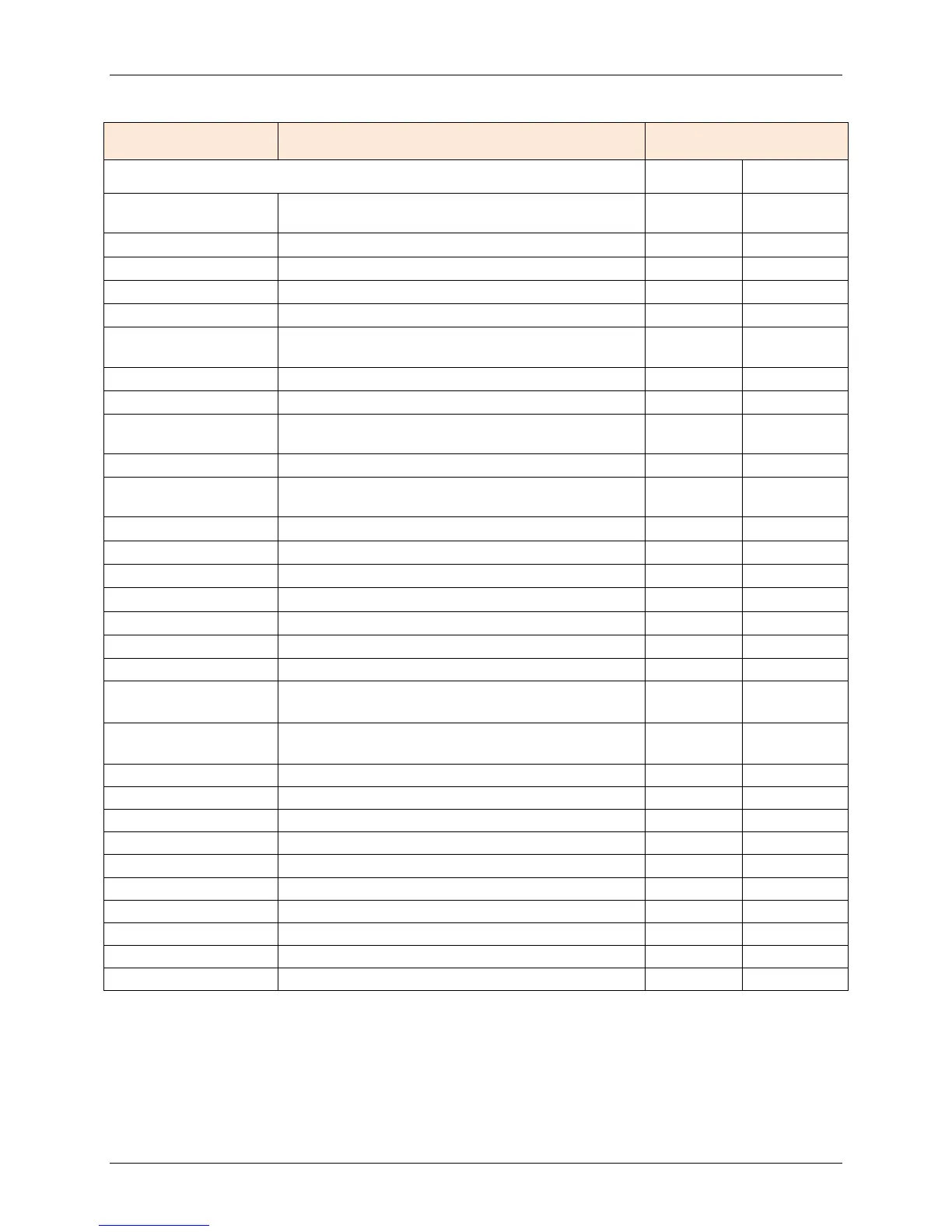
Table 5-6: EXPERT Menu
LEVEL DESCRIPTION ENTRY
INSTALLATION DEFAULT RANGE
BUS-ID HS
Boiler Bus address only for cascade of E8
controllers
---- (01 ÷ 08)
The heating circuits are sequentially numbered.....
The heating circuits are sequentially numbered.....
Outdoor sensor power supply
Bus terminating resistor
EBUS SUPPLY
Switching eBUS supply on/off in realtion to
01 (00 ÷ 01)
00 no time master; 01 controller is time master
Protects the HS from overheating
MIN T-COLL
Decreased condensation build-up in HS with low
heat requirement
50°F (50 ÷ 176)
Protects the HS from overheating
MIN T-HS2
Decreased condensation build-up in HS with low
heat requirement
104°F (50 ÷ 176)
Only for 0-10V input/output
Starting with this voltage level
Dyn. Switching hysteresys stage 1
FOUND MODULS
Display of burners automatically reported via
BUS
0 (0÷30 min)
CAP/MODULE
After restarting the controller searches the bus
systems
---- (0÷1000)
Number of stages for HW operation
Required system output [in %]
Currently remaining value
Maximum temperature of the heat generator
Dynamic heat generator connection
Dynamic heat generator deactivation
Resetting time for I-Controller