15
-10
-5
0
5
10
15
20
25
30
35
40
45
50
46810121416 °C
(1)
2
(2)
(3)
(4)
18
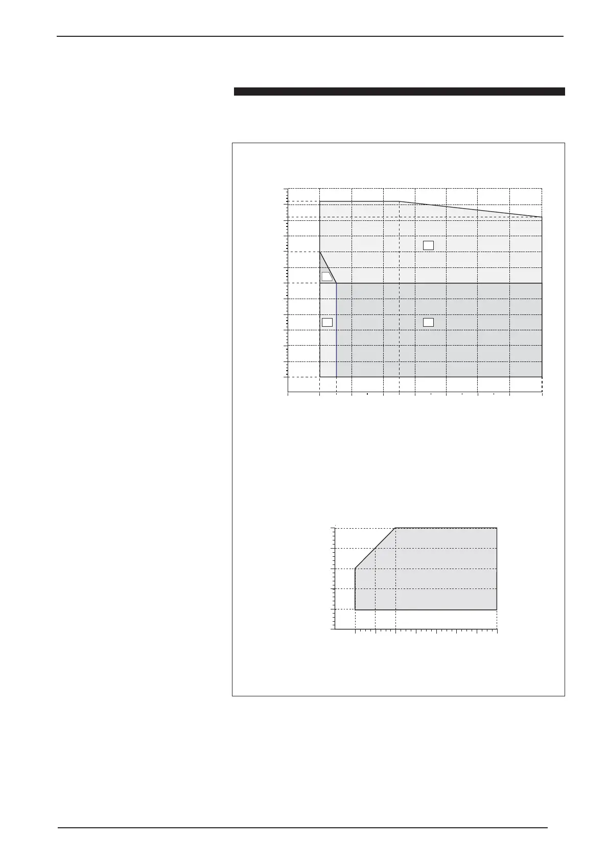
Figure 1 opposite shows the operating
limits of the ANZ units both for cooling
and for heating.
Figure 2 shows the multiplicational
coefficients to be applied to the yielded
rated cooling capacity data and the
input power.
Figure 3 shows the multiplicational
coefficients to be applied to the yielded
rated cooling thermal data and the input
power.
Figure 4 shows the correction
coefficients, if used with glycol water
and correction coefficients to be used
in accordance with the degree of
exchanger dirtying.
Page 15 shows the data concerning the
acoustic power and pressure emitted by
the equipment.
N.B.:
The devices in their standard
configurations are not suitable for
installation in salty environments. The
maximum and minimum water flow rate
limits are shown on the curves of the
pressure drop diagrams. Reference should
be made to the diagram opposite for the
operation limits.
Please contact the AERMEC technical
sales office in the event it is necessary to
operate the machine outside the limits
indicated in the diagram.
If the machine is to be placed in a
particularly windy position, wind breaks
must be provided to avoid the DCPX
operating in an unstable condition.
Temperature of water produced (∆t=5°C)
External air temp. d.b. °C
how to choose
Operating limits
-15
-10
15
35
30
40
45
50
Twc
-5 0 5
10 20
Temperatura acqua prodotta °C
Tae
Operating limits (HEATING)
fig. 01
(1) = Standard functioning
(2) = Glycol water
(3) = DCPX
(4) = DCPX + Glycol water