47Aermec cod. 5806715_00 12.01
NRP 0200-0750
EN
FASEFASEFASE
27. COLLEGAMENTI ELETTRICI
The NRP mul purpose units are completely wired
at the factory and only require connec on to the
electrical mains, downstream from a unit switch,
according to that envisioned by the Standards in force
on this subject in the country of installation.
It s also advised to check that:
1. The electrical mains features are suitable for the
absorption values indicated in the electrical data
table, also taking into consideration any other
machines operating at the same time.
2. The unit is only powered when installation has
been completed (hydraulic and electric).
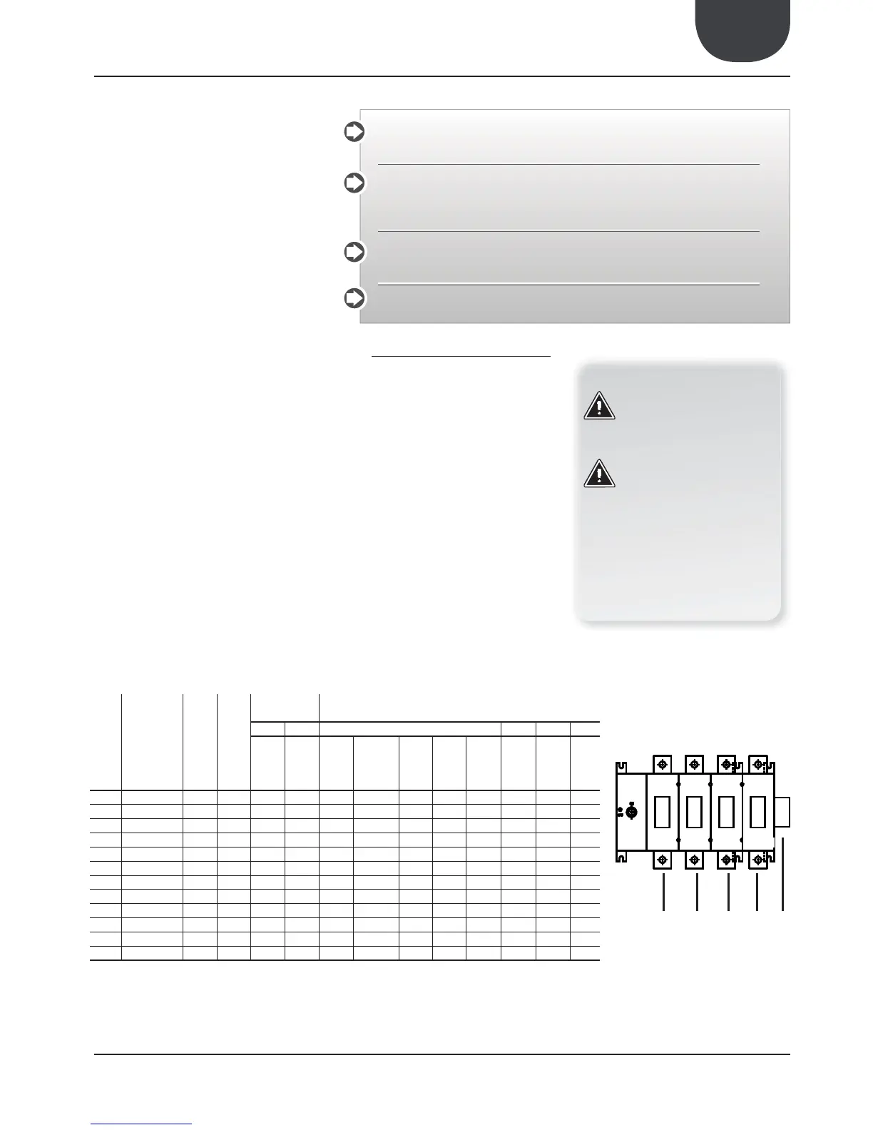
3. Respect the connection indications of the phase,
and earth wires.
4. The power supply line must have a relevant
protection mounted upstream against short
circuits and dispersions to earth, which isolates
the system with respect to other utilities.
5. The voltage must be within a tolerance of
±10% of the nominal power supply voltage of
the machine (for unbalanced three-phase unit
max 3% between the phases). Whenever these
parameters are not respected, contact the
electric energy public body.
6. For electric connections, use the cables with
double isolation according to the Standards in
force on this subject in the different countries.
MANDATORY
1. The use of an omnipolar magnet circuit breaker
switch is mandatory, in compliance with the
IEC-EN Standards (contact opening at least 3
mm), with suitable cut-off power and differential
protection on the basis of the electric data table
shown below, installed as near as possible to the
appliance.
2. It is mandatory to make an effective earth
connection. The manufacturer cannot be held
responsible for any damage caused by the lack of
or ineffective appliance earth connection.
3. For units with three-phase power supply, check
the correct connection of the phases.
27.1. ELECTRIC DATA TABLE
The cable section shown in the table are recommended
for maximum lengths of 50m.
For longer lengths or different cable laying, it is up to
the PLANNER to calculate the appropriate line switch,
the power supply line as well as the connection to the
earth wire and connection cables depending on:
• the length;
• the type of cable;
• the absorption of the unit and the physical
location, and the ambient temperature.
All the electrical opera ons must be carried out bySTAFF IN POSSESSION OF THE NECESSARY
QUALIFICATIONS BY LAW, suitably trained and informed on the risks related to these
opera ons.
The characteris cs of the electrical lines and of the related components must be determined
by STAFF QUALIFIED TO DESIGN ELECTRICAL SYSTEMS, in compliance with the interna onal
and na onal regula ons of the place of installa on of the unit and in compliance with the
regula ons in force at the moment of installa on.
For the installa on requirements refer only to the electrical diagram supplied with the
appliance. The electrical diagram along with the manuals must be kept in good condi on and
ALWAYS AVAILABLE FOR ANY FUTURE SERVICING ON THE UNIT.
It is mandatory to verify that the machine is water ght before making the electrical connec ons
and it must only be powered up a er the hydraulic and electrical works have been completed.
NRP SIZE
Power supply
Compressors [n°]
Fans [n°]
TOTAL
ABSORPTION
RECOMMENDED CABLE CROSS-SECTION
L.R.A.: F.L.A.: SEC. A SEC. B EARTH IL
[A] [A]
Phases
[n°]
Cables
for single
phase [n°]
Cable
cross-
section
[mm
2
]
Neutral
cross-
section
[mm
2
]
Total
cables
[n°]
[mm
2
] [mm
2
] [A]
0200
400V/3N/50Hz
2 6 119 36 3+N 1 10 10 4 4 1,5 63
0240
400V/3N/50Hz
2 6 150 41 3+N 1 16 16 4 4 1,5 63
0280
400V/3N/50Hz
2 6 155 46 3+N 1 16 16 4 1,5 16 63
0300
400V/3N/50Hz
2 8 184 53 3+N 1 16 16 4 1,5 16 63
0330
400V/3N/50Hz
2 8 190 58 3+N 1 25 16 4 1,5 16 80
0350
400V/3N/50Hz
2 8 200 63 3+N 1 25 16 4 1,5 16 80
0500
400V/3N/50Hz
3 2 214 76 3+N 1 35 25 4 1,5 16 100
0550
400V/3N/50Hz
3 2 220 81 3+N 1 35 25 4 1,5 16 100
0600
400V/3N/50Hz
4 2 232 100 3+N 1 50 25 4 1,5 25 125
0650
400V/3N/50Hz
4 2 243 112 3+N 1 70 35 4 1,5 35 160
0700
400V/3N/50Hz
4 3 261 122 3+N 1 70 35 4 1,5 35 160
0750
400V/3N/50Hz
4 3 320 144 3+N 1 95 50 4 1,5 50 200
neutro
PE
400V/3N/50Hz
ATTENTION
Check the tightening of all power
wire terminals on commissioning
and after 30 days from start-
up. Subsequently they must be
checked every six months.
Loose terminals can cause
overheating of the cables and
components.
ATTENTION
It is prohibited to use the water
pipes to earth the appliance.
KEY
F.L.I.: Maximum input power
F.L.A.: Maximum input current
L.R.A.: Initial starting current
Sec A: Power supply
3+N: 3 phases + neutral
Sec B: Controls and safety device connection
EARTH: Earth wire to connect to unit
IL: Main switch
 Loading...