16
Fig. D
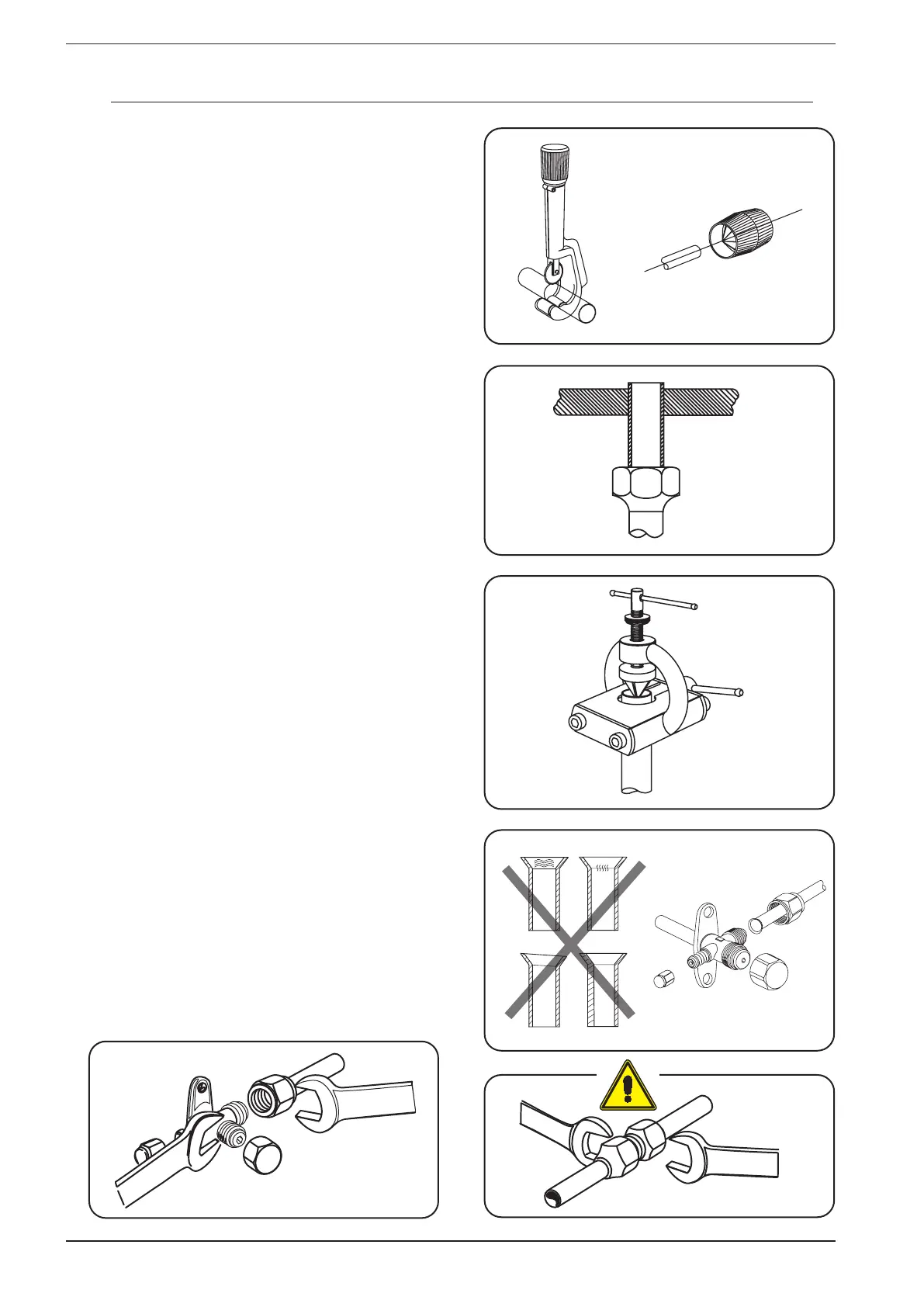
To prepare the copper pipes, proceed as follows:
1. Measure the inner and outer pipe precisely.
2. Use a pipe which is slightly longer than the measurement taken.
3. Cut the copper pipes to measure using the pipe cutter and smooth the
ends with a pipe reamer (Fig. A);
4. Insulate the pipes and fit conical nuts before fitting collars to the ends
of the pipes (Fig. B);
5. To fit the conical collars at 45° use a bevel edging tool (Fig. C);
6. Deburr the inside of the refrigerant pipe.
7. During reaming, the end of the pipe must be above the reamer to pre-
vent the ingress of dust into the pipe.
8. Ensure that the inside of the pipe is clean and free of any swarf.
9. Check the conical surface is in line with the pipe, and that it is smooth,
without fractures and of uniform thickness (Fig. D).
To make the cooling connections, proceed as follows:
1. Feed the lines, the condensate discharge pipe and the electric ca-
bles through the hole in the wall, aligning the ends of the lines with the
couplings on the units (the lines are fitted on site, before feeding them
through the hole, seal the end with tape to prevent the ingress of dirt).
2. Shape the refrigerant lines until they are aligned with the couplings on
the outdoor unit.
3. (You are advised to avoid bending the refrigerant lines with a radius of
less than 100mm, so as not to crush the pipe section).
4. If the difference in height between the indoor unit and the outdoor unit
exceeds 3 metres (H1 - H2), and the outdoor unit is positioned above the
indoor unit, it is recommended to provide a siphon or a loop on the gas
pipe to facilitate the return of lubricating oil to the compressor.
5. Before connecting the pipes to the unit, check the position is correct.
6. Remove the protection from the ends of the refrigerant lines.
7. Clean the joint surfaces so the tightening surfaces are in perfect con-
tact.
8. Lubricate the connections inside and out with a thin layer of engine oil.
9. Connect and tighten the pipes to the outdoor unit; use a wrench and
counter-wrench to avoid subjecting the machine structure to torsion
(Fig. F).
10. Connect and tighten the refrigerant lines on the indoor unit; use a
wrench and counter-wrench to avoid subjecting the pipes to torsion
(Fig. E).
11. Respect the tightening torque indicated in the table.
Fig. A
Fig. B
Fig. C
Fig. E
Fig. F
10.5. FITTING THE REFRIGERANT LINES