26
5 ELECTRIC CONNECTIONS
i
All electrical operations must
be performed BY STAFF WITH
NECESSARY LEGAL REQUISITES,
trained and informed regarding risks
correlated to these operations.
i
The features of the electric lines
and relative components must be
determined by STAFF QUALIFIED
FOR THE DESIGN OF ELECTRICAL
PLANTS, complying with national
and international regulations of the
place of installation of the unit.
i
All electrical connections must
comply with legislation in force at
the time of installation.
i
Reference must be made to the
wiring diagram supplied with the
appliance, for installation to be
performed correctly. The wiring
diagram, along with the manuals,
must be kept carefully and
made AVAILABLE FOR FUTURE
INTERVENTIONS ON THE UNIT.
4.1 LINES AND UNIT ELECTRICAL
DATA
NOTE
The sections of the cables and
dimensioning of the line switch stated
in TAB 4.1.1 are purely indicative or
recommended for a maximum length of
50 m. It is the installer's responsibility to
appropriately dimension the power supply
line and the earth connection depending
on:
- the length
- the type of cable
- the absorption of the unit, physical
location and environmental
temperature.
4.2 CONNECTION TO THE ELECTRIC
POWER SUPPLY MAINS
- Check that the electric power supply
line has features in compliance with
the potential that it must support.
- Protect the cables using fairleads with
suitable lengths.
-
The unit is completely wired in the
factory and requires an electric power
supply to be started-up according
to the indications on the unit's plate,
intercepted with line protections.
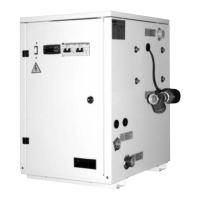
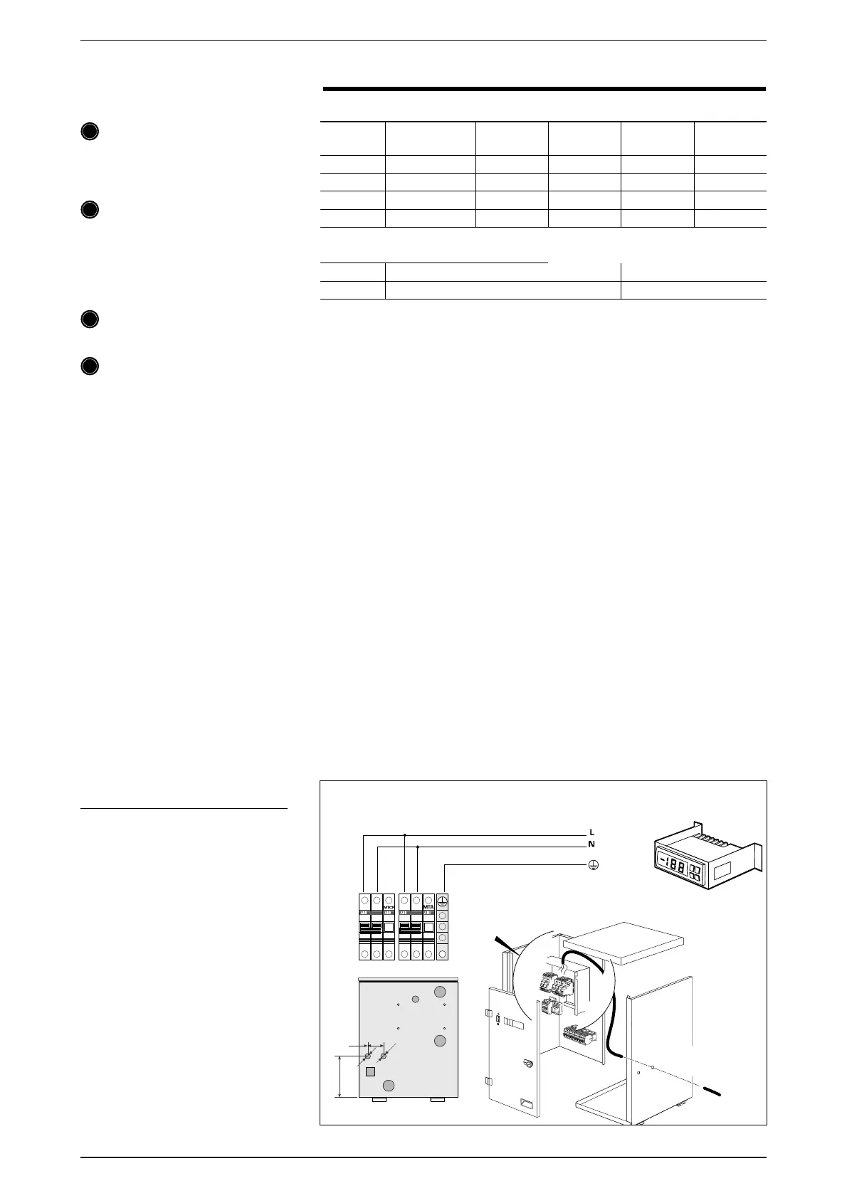
The units are prepared for electric
connections with fairleads on the right
side panel (fig. 01), one for the electric
power supply, the other for the eventual
connection of the PR3 or SDP. For
installation refer to the wiring diagram
supplied with the appliance and follow
these simple operations (fig. 01)
1. Open the front hatch by acting on the
1/4 turn closure
.
2. Pass the electric power supply cable
from the fairlead.
3. Connect the earth, the line and then
neutral.
- Before powering the unit electrically
ensure that all protections that
were previously removed have been
replaced correctly.
NOTE:
Check the tightness of all power wire
clamps on commissioning and after
30 days from being put into service.
Successively, check the tightness of all
power clamps every six months.
Loosened clamps can cause overheating
of cables and components.
The units in the VENICE series leave the
factory prepared also to be controlled
from remote panels or by simple switches
(on/off switch, heating/cooling).
If switches are installed for remote
control, the connections to the unit
terminal board must be realised using
cables with suitable section TAB 4.1.1. The
max. distance allowed is 30 m for the
PR3.
ATTENTION
If the remote panel has not been
connected or if it is to be removed
successively, parameters H06 and
H07 must be set at 0 on the board on
the machine (fig.01), otherwise the unit
cannot be piloted by the control on the
same. Refer to the user manual for this
operation.
VENICE (IL) A
SEC. A
(mm
2
)
SEC. B
(mm
2
)
PE
(mm
2
)
015 230V
~
- 50 Hz 13 2.5 0.5 2.5
020 230V
~
- 50 Hz 16 4 0.5 4
025 230V
~
- 50 Hz 20 4 0.5 4
030 230V
~
- 50 Hz 25 6 0.5 6
Tab. 4.1.1
KEY
IL
Master switch
SEC.B
Remote panel power supply
SEC.A
Power supply
PE
Earth
uÛ
uÛ
Power supply
cable
Fairleads
fig. 01
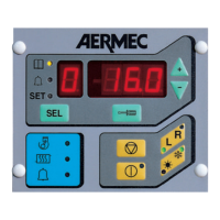
Display

 Loading...