MAINTENANCE MANUAL
IFR 6000
2-2-3
Page 10
Aug 1/06
(7) DME Reply Delay and Range
TEST EQUIPMENT: Oscilloscope
ATC-1400A
6dB Splitter
Pulse Detector
VERIFICATION FAILURE: If any step in this procedure fails or is out of tolerance,
this indicates a failure in the Test Set. Refer to
Troubleshooting for corrective action.
STEP PROCEDURE
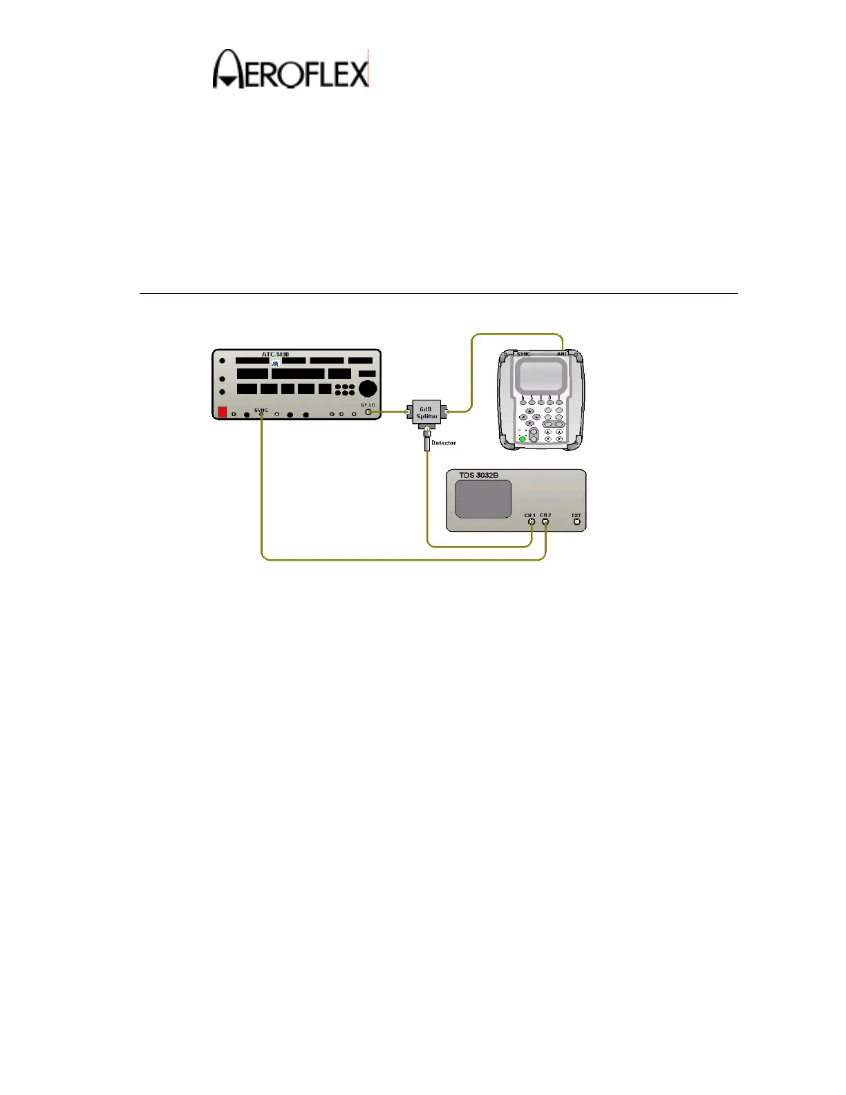
1. Make the connection as shown in Figure 5.
DME Reply Delay and Range Test Connection
Figure 5
2. Set the ATC-1400A switch settings as follows:
FREQ/Function Select: 1041 MHz X
MAN/AUTO/MAN STEP: MAN
DME Reply Efficiency: 100%
SYNC: T
D
RF LEVEL: −2dBm
CW/NORM/OFF: NORM
PRF/SQTR: 100
DME P2 Toggle Switch: CAL
Self-Interrogation: ON
Remaining toggle switches OFF/CAL position
3. Set Scope to trigger off CH2 at 2V and set CH1 to 50Ω impedance, invert on.
4. Press the SETUP key twice to display the SETUP-DME screen.
5. Verify the RF PORT shows ANTENNA. If necessary, change it to ANTENNA.
 Loading...