MAINTENANCE MANUAL
IFR 6000
2-2-3
Page 25
Aug 1/06
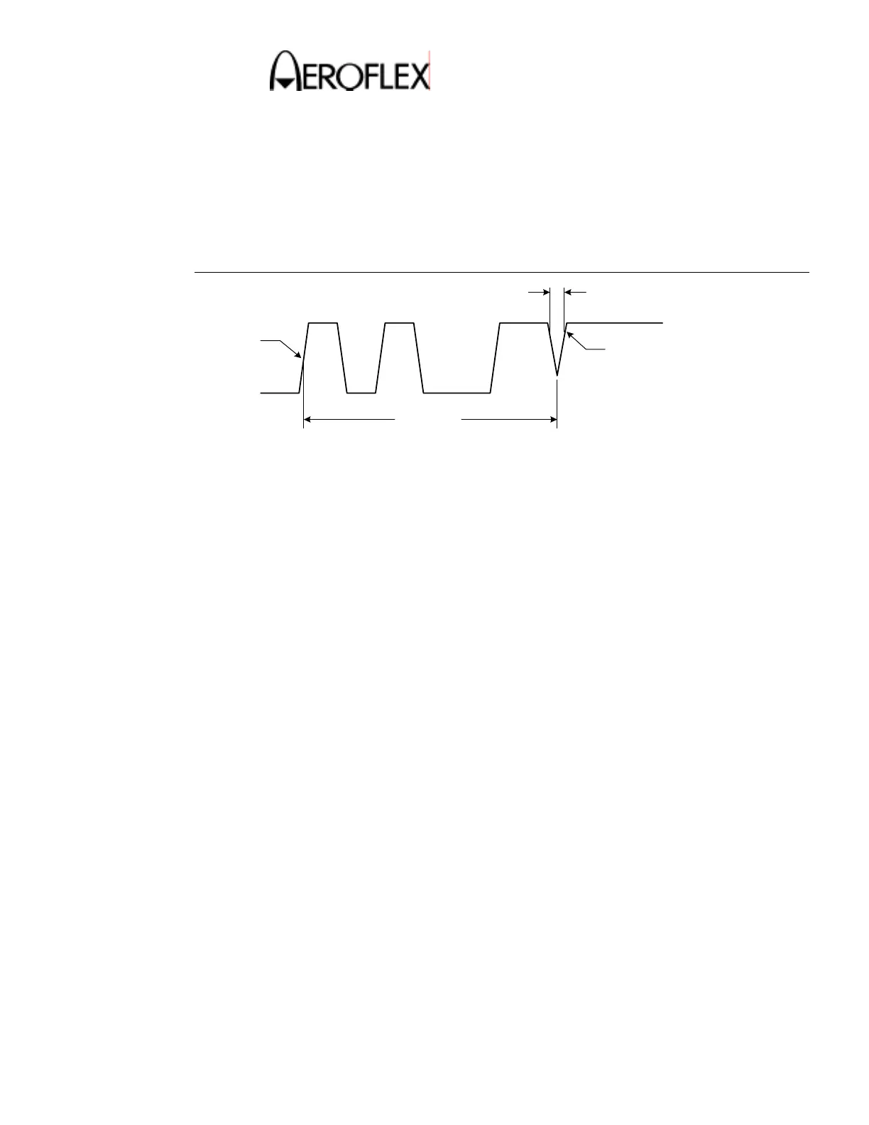
(15) XPDR Pulse Characteristics – Mode S
TEST EQUIPMENT: Oscilloscope
Pulse Detector
VERIFICATION FAILURE: If any step in this procedure fails or is out of tolerance,
this indicates a failure in the Test Set. Refer to
Troubleshooting for corrective action.
STEP PROCEDURE
P1 P2 P6
P1 to SPR
80% POINT
PHASE TRANSITION TIME
50% POINT
Mode S Interrogation
Figure 11
1. Connect the Detector directly to the ANT port.
2. Connect the other end of the Detector to Scope CH1.
3. Connect the UUT SYNC port to Scope CH2.
4. Set Scope to trigger off CH2 at 2V and CH1 to 50-ohm impedance, invert on.
5. Press the SETUP key to display the SETUP-XPDR screen.
6. Verify the RF PORT shows ANTENNA. If necessary, change it to ANTENNA.
7. Press the DIAG Key to display the XPDR DIAGNOSTICS screen.
8. Press the SELECT Soft Key to display the XPDR DIAG-FORMAT 0 screen.
9. Set up the UUT as follows:
RFLVL: -3dBm
PRF: 100
ADDRESS: 000000
SLS: OFF
10. Press the RUN TEST Soft Key.
11. Use the Scope to verify the following pulse spacing:
P1-P2 equals 2.0µS ± 25nS
P1-P6 equals 3.5µS ± 25nS
P1-SPR equals 4.75µS ± 25nS
 Loading...