MAINTENANCE MANUAL
IFR 6000
2-2-3
Page 58
Aug 1/06
(30) TCAS Mode S Reply
TEST EQUIPMENT: IFR 6000
VERIFICATION FAILURE: If any step in this procedure fails or is out of tolerance,
this indicates a failure in the Test Set. Refer to
Troubleshooting for corrective action.
STEP PROCEDURE
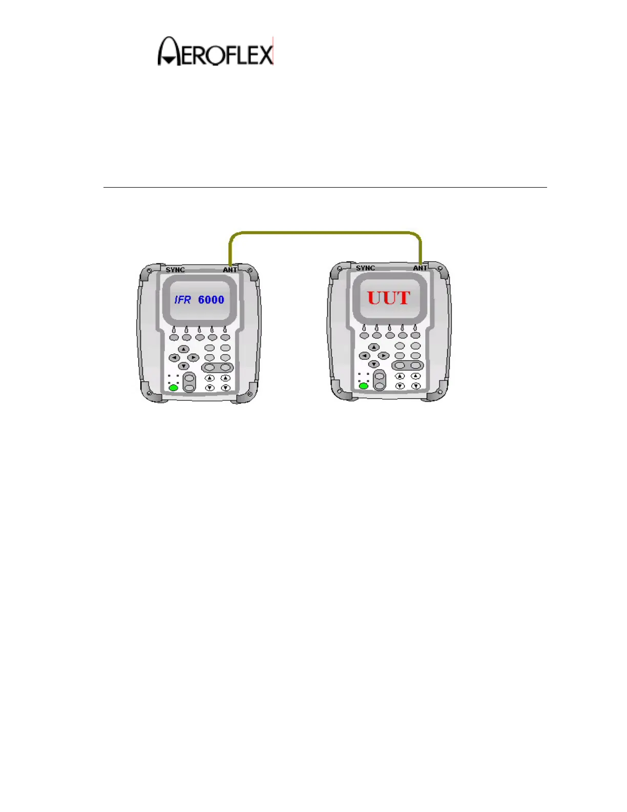
1. Make the connection as shown in Figure 20.
TCAS Mode S Reply Test Connection
Figure 20
2. Press the SETUP key on the IFR 6000 to display the SETUP-XPDR screen.
3. Verify the RF PORT shows ANTENNA. If necessary, change it to ANTENNA.
4. Press the DIAG Key to display the XPDR DIAGNOSTICS screen.
5. Use the key to highlight the DOWNLINK FORMAT 0 line.
6. Press the SELECT Soft Key to display the TCAS DIAG-DF0 screen.
7. Set up the IFR 6000 Format 0 screen as follows:
RX ATTEN: 30 dB
RFLVL: –10 dBm
PRF: 100
SLS: OFF
ADDRESS: A92493
8. On the UUT, press the TCAS and then the SETUP key to display the SETUP-
TCAS screen.
9. Verify the RF PORT shows ANTENNA. If necessary, change it to ANTENNA.
 Loading...