MAINTENANCE MANUAL
IFR 6000
2-2-3
Page 47
Aug 1/06
(25) TCAS Reply Pulse Characteristics
TEST EQUIPMENT: Oscilloscope
Pulse Detector
VERIFICATION FAILURE: If any step in this procedure fails or is out of tolerance,
this indicates a failure in the Test Set. Refer to
Troubleshooting for corrective action.
STEP PROCEDURE
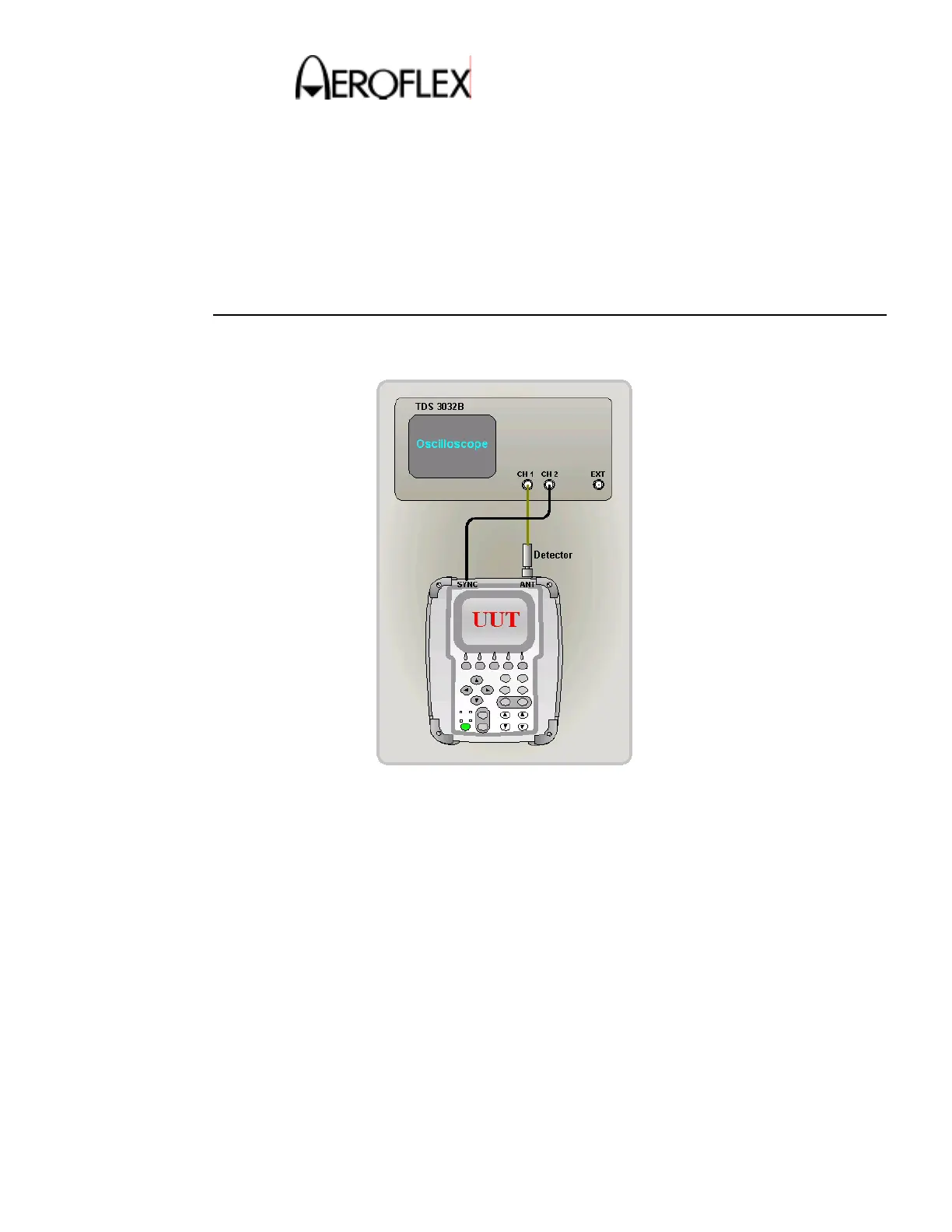
1. Make the connection as shown in Figure 14.
TCAS Reply Pulse Characteristics Test Connection
Figure 14
2. Set Scope CH1 to 50-ohm impedance, invert on.
3. Set the Scope to trigger off CH2 at 2V.
4. Press the TCAS and then the SETUP key to display the SETUP-TCAS screen.
5. Verify the RF PORT shows ANTENNA. If necessary, change it to ANTENNA.
6. Press the DIAG Soft Key to display the TCAS-DIAGNOSTICS screen
7. Press the Select Soft Key to display the TCAS-DIAG MODE C REPLY screen.
8. Set the UUT as follows:
Level : –2 dBm
ALT: 30300 ft.
 Loading...