MAINTENANCE MANUAL
IFR 6000
2-2-3
Page 13
Aug 1/06
STEP PROCEDURE
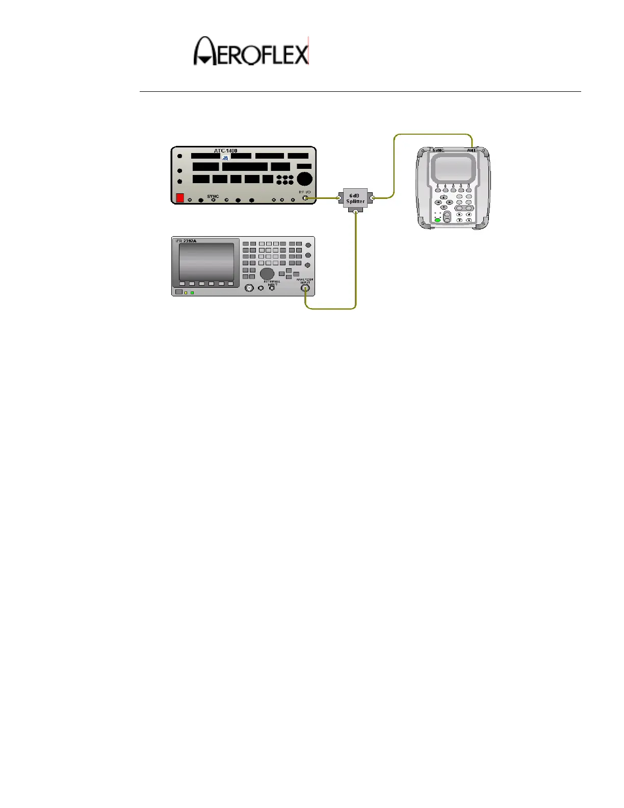
8. Make the connection as shown in Figure 6.
DME Echo Reply Position and Amplitude Test Connection
Figure 6
9. Set Spectrum Analyzer as follows:
Frequency: 978MHz
Input Attn: 20dB
RBW: 5MHz
VBW: None
Span: 0Hz
REF: –5dB
Sweep: 5µS
Trigger Video
Trig. Mode: Normal
Scale: 5dB
Marker: On
10. Measure and record the level of P1 reply pulse.
11. Set the trigger delay to 370µS.
12. Measure and record the level of P1 echo reply pulse.
13. Verify the echo reply pulse level is –11dB ± 1dB below the P1 reply level.
14. Press the STOP TEST Soft Key.
15. Set ECHO to OFF.
 Loading...