MAINTENANCE MANUAL
IFR 6000
2-2-3
Page 18
Aug 1/06
STEP PROCEDURE
6. Measure and record the pulse spacing of Y channel P1 to P2 on the scope.
7. Change the ATC-1400A settings as follows:
FREQ/Function Select: 1041 MHz X
DME P2 Switch: CAL
RF LEVEL Control: −10dBm
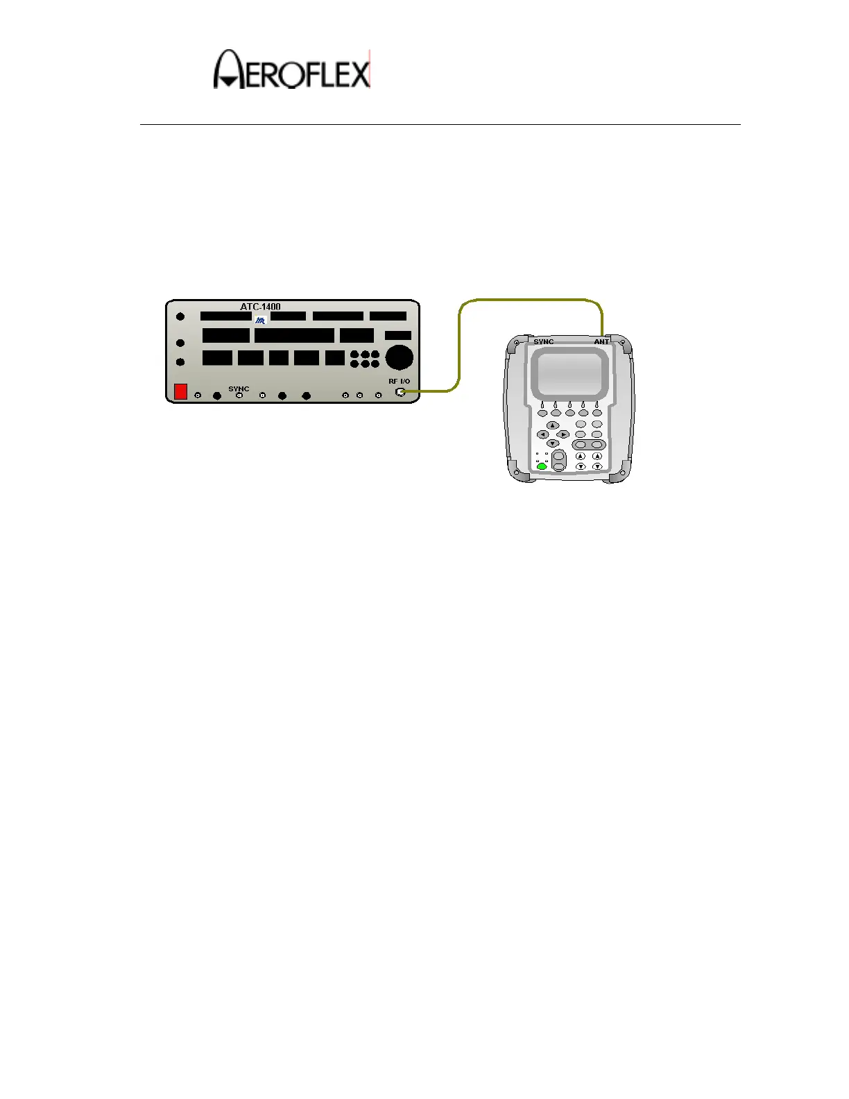
8. Make the connection as shown in Figure 9.
DME Measurement - Interrogation Pulse Timing
Test Connection 2
Figure 9
9. Press the SETUP key twice to display the SETUP-DME screen.
10. Verify the RF PORT shows ANTENNA. If necessary, change it to ANTENNA.
11. Set the ANT RANGE to 250ft.
12. Press the DME Key to display the DME screen
13. Set up the UUT as follows:
RFLVL: -64.6dBm (-2dBm)
CHAN: 17X
Rate: STOP
Range: 0.0nm
14. Press the RUN TEST Soft Key.
15. Verify the following pulse width and spacing values on the UUT.
P1 Pulse Width equals recorded P1value ± 0.05µS
P2 Pulse Width equals recorded P2 value ± 0.05µS
P1-P2 Spacing equals recorded X channel P1-P2 value ± 0.02µS
16. Press the STOP TEST Soft Key.
17. Change the ATC-1400A settings as follows:
FREQ/Function Select: 1041 MHz Y
DME P2 Switch: +∆
 Loading...