Do you have a question about the AES 7788F and is the answer not in the manual?
| Model | AES 7788F |
|---|---|
| Category | Gateway |
| Operating Temperature | 0°C to 40°C |
| Storage Temperature | -20°C to 70°C |
| Humidity | non-condensing |
| Ports | 4x 10/100/1000Base-T Ethernet, 2x SFP+ |
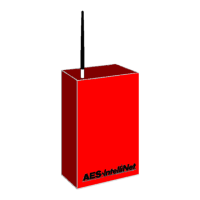
Overview of the AES 7788F Subscriber Unit and its RF Signaling Device capabilities.
Provides a general overview of the 7788F Subscriber Unit's function as an RF communicator.
Lists new features incorporated into the 7788F unit compared to previous AES IntelliNet products.
Describes the physical housing, self-enrollment into the AES-IntelliNet network, and signal transmission.
Details the steady-state and peak DC current draw for the unit.
Provides guidance on required battery sizes for different configurations of the 7788F unit.
Describes the included RF module (transceiver) and its standard antenna specifications.
Outlines essential safety precautions, compliance with codes, and potential hazards.
Details safety precautions regarding periodic testing, temperature exposure, and physical impact.
Lists detailed technical specifications including size, weight, power input, temperature range, and humidity.
Lists various UHF antenna options with their construction, usage, length, and part numbers.
Details available coaxial cable options, connectors, and crimp tools for antenna connections.
Provides recommendations for selecting and installing coaxial cables and antennas to minimize signal loss.
Discusses installation requirements specific to commercial fire and burglary applications, including tamper protection.
Illustrates suggested locations for mounting tamper switches on the enclosure for security.
Specifies the required AC power input voltage and VA rating for UL certified installations.
Details backup battery requirements for commercial fire signaling applications.
Explains the programming requirement for EOL alarm inputs for supervised or fire applications.
Describes how to connect the J4 output for local trouble annunciation in fire or burglar alarm systems.
Provides a general overview of the 7788F unit's components and its role in alarm communication.
Details installation guidelines, including wiring, location choice, and mounting the enclosure.
Offers advice on antenna mounting height, proximity to metal, grounding, and vertical orientation.
Illustrates the grounding and surge protector setup for a remote antenna installation.
Shows a diagram of the 7788F enclosure assembly, highlighting key components like the PCB and battery.
Provides a general overview of wiring connections on the 7788F board with typical examples.
Illustrates user connections to the 7788F board, including programmer, zone inputs, and power.
Describes the RS-232 port for connecting programmers and accessory modules.
Details the Antenna Cut/Trouble output, its function for local reporting, and its specifications.
Details Earth Ground connection requirements and methods for proper grounding.
Further explains how the J4 relay's state indicates fault conditions like loss of communication.
Shows a diagram illustrating the J4 Antenna Cut / Trouble Relay contacts (C, NC, NO).
Details connecting a local annunciator to the J4 trouble output for indicating subscriber trouble.
Provides an overview of zone programming options and wiring for various input states.
Presents a chart detailing zone programming options and their corresponding input electrical states.
Explains the maximum resistance for EOL inputs and the required wire resistance.
Illustrates the minimum required wiring for UL Listed Fire installation using EOL supervision.
Illustrates wiring zone inputs to voltage outputs, noting it's not approved for UL/Fire alarm.
Guides through the process of powering up the unit and its initial network enrollment.
Lists error codes displayed during the unit's self-test and their meanings.
Describes the function of the four LED indicators on the main circuit board.
Details the various blink patterns of the ALM LED and their corresponding status meanings.
Explains limitations on remote programming, especially for UL and Fire Alarm installations.
Details the procedure for programming the unit ID and system cipher code.
Guides on setting timing parameters like Check-In Interval and AC Fail reporting delay.
Explains reporting delay, AC reporting delay, and options for setting these parameters.
Covers programming zone inputs for EOL, Fire Supervised, or Bypass configurations.
Details the sequence for setting zone programming options and restorals.
Explains programming options for repeating capability and suppressing AC Fail reports.
Guides on using the Reset RAM function to return the unit to factory default settings.
Describes the final check and network enrollment process after programming.
Details how to perform a quick diagnostic check of the unit's status and network connectivity.
Explains functions for viewing network data traffic for diagnostics.
Describes how to activate the transmitter for testing radio parameters with external equipment.
Guides on reviewing the current state of each subscriber zone input.
Explains how to display and interpret the subscriber's current routing table information.
Further details on interpreting routing table fields like Link Layer and NetCon.
Details sending and receiving text messages between the subscriber and the central station.
Provides a quick reference for handheld programmer commands and PC terminal equivalents.
Details how to program the unit using a PC instead of a handheld programmer.
Lists tests to perform at the installation site, requiring central station response.
Discusses common causes of RF failure or trouble and suggested solutions.
Lists the standard items included with the 7788F Subscriber unit.
Provides contact details for AES Corporation, including website, phone, and fax numbers.
Details the owner warranty, technology license, and the procedure for returning units for service.
 Loading...