24 Agilent 35670A Supplement
4 Service Guide
To troubleshoot IIC bus failures
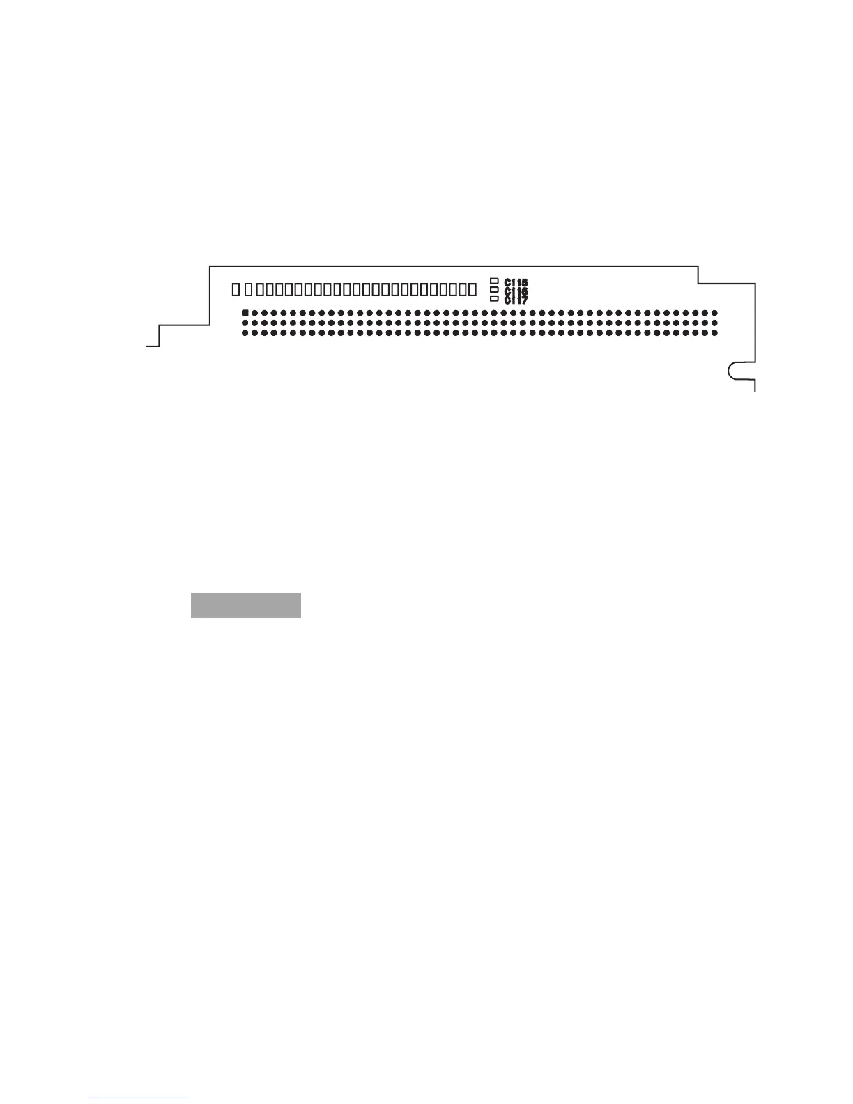
A new illustration above step 2 shows new connector pin- outs:
✔ Step 2. Check the serial clock (SCL).
• Attach a logic probe to A17 P1- 15 (SCL) or P10 pin B10.
• Set the power switch to on (|).
• Press S5 (reset switch) while monitoring A17 P10 pin B10
(SCL), the power- on LEDs, and the display.
The TTL logic level of the SCL signal should toggle continuously
while Booting System is displayed. The following failure message
should be displayed after Booting System and the display grid
should appear about two minutes after power up.
Front Panel failure information:
keyboard IIC chip fails:
IIC: No Device Acknowledge
Key stuck: 32
A power-on test has failed. Refer
servicing to qualified personnel.
Press Start key to attempt to continue
Power-up.
• If the SCL signal does not toggle after S5 is pressed, the A17
CPU assembly is probably faulty
Page in original guide 4-26,27
Figure 9 A17 CPU motherboard (P10) connector pin locations
A1
B1
C1
A50
B50
C50
2
3
4
NOTE
S5 (reset switch) is a normally open momentary switch. A press of the
switch, S5, can be simulated by temporarily shorting TP214(RESET
INn) to TP215 (DCOM).

 Loading...


