EasyManuals Logo
Home>Agilent Technologies>Measuring Instruments>35670A

Agilent Technologies 35670A Service And Operator's Guide

Agilent Technologies 35670A
52 pages
To Next Page IconTo Next Page
To Previous Page IconTo Previous Page
Page #26 background imageLoading...
Page #26 background image
26 Agilent 35670A Supplement
4 Service Guide
To troubleshoot fast bus failures
New table:
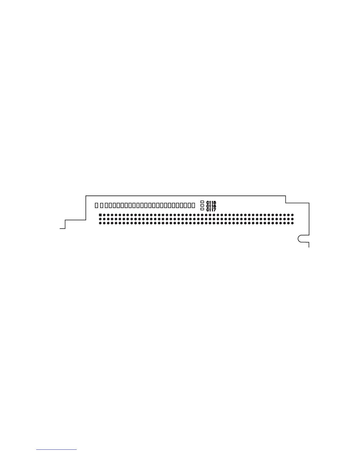
New illustration showing location of motherboard connector
pins.
Page in original guide 4-30
A17 P10 Pin Signal Name TTL Logic State in Test Mode
B14, C14, B15, C15, B16 FA1 to FA5 Toggling
B22 ECLK Toggling
B24 FSELAn Toggling
C12 BRESETn Low
C19 FRW Toggling
C23 FIFOENn High
C24 FSELSn Toggling
Figure 11 A17 CPU motherboard (P10) connector pin locations
A1
B1
C1
A50
B50
C50
2
3
4

Other manuals for Agilent Technologies 35670A

Questions and Answers:

Question and Answer IconNeed help?

Do you have a question about the Agilent Technologies 35670A and is the answer not in the manual?

Agilent Technologies 35670A Specifications

General IconGeneral
BrandAgilent Technologies
Model35670A
CategoryMeasuring Instruments
LanguageEnglish

Related product manuals