42 Agilent 35670A Supplement
4 Service Guide
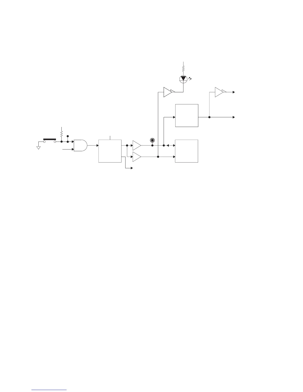
Reset logic all references to S2 are changed to S5 and there is a
new block diagram.
IIC (Inter_IC) controller the bullet referring to A8 memory is
replaced:
• A17 CPU (Real time clock, EEPROM)
Disk Controller Disregard the final sentence referring to
reversed operation.
Frame Memory Consists of four SRAM chips.
Figure 21 Reset logic
To battery-backed SRAM control circuit
RESET
+5V
RSTn
Buffer
+5V
P8(S)
Reset
RSTn
HALTn
MPU
Reset
Generator
RESET
RESETn
+5V
S5
PVALID
(from power supply)
RUN
(GREEN)
To Disk I/F
TO IIC Controller
To A11 Keyboard Controller
To Disk I/F
To Display I/F
To HP-IB Interface
To MFP
To MC56001
To DMA Controller
To A6 Digital
To A5 Analog
DCOM
RESETINn
test point

 Loading...


