26 Chapter 2
Agilent 4072/4073 Preinstallation Guide, Edition 4
Site Preparation
Electrical Requirements
Main power cable
You must prepare the power cables to connect the 4072/4073 tester to the switchboard because it is not bundled
with the tester. This chapter describes how to prepare the main power cables.
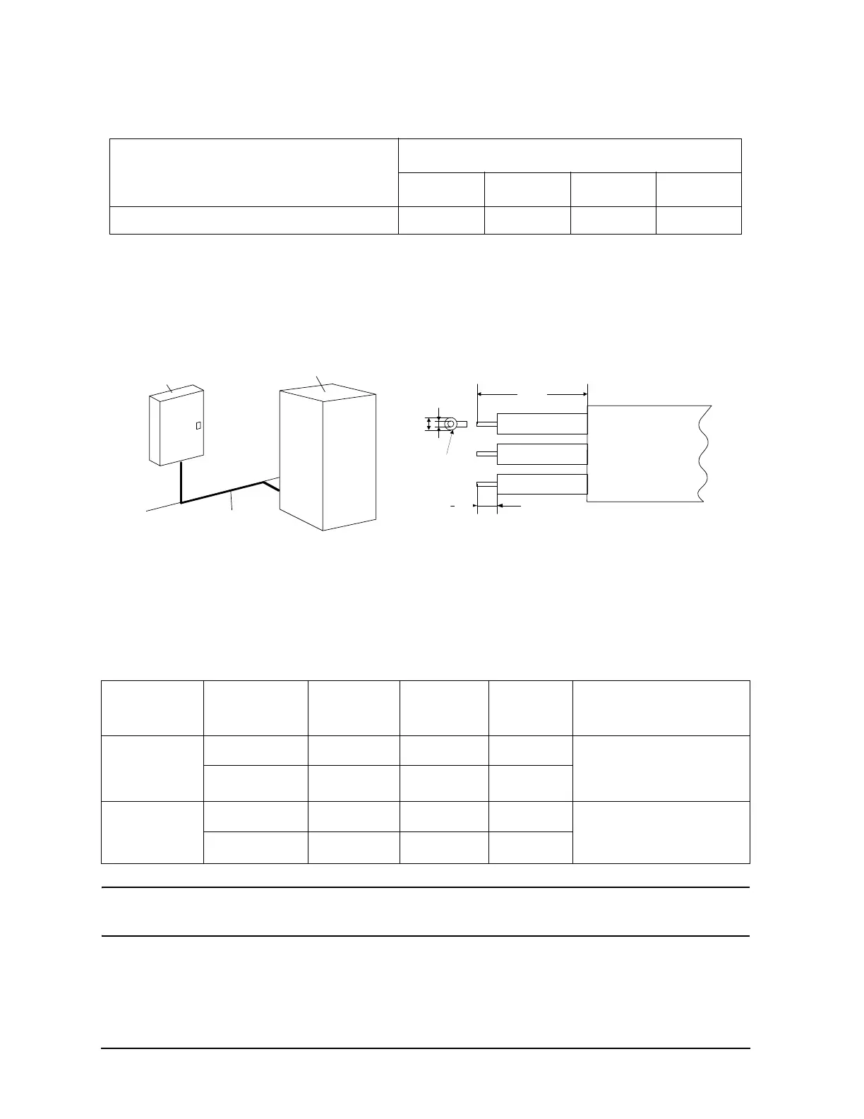
Figure 2-11 Connecting power cable
When you connect the ground wire to the PDU of the system cabinet, use the terminal as shown in Figure 2-11.
Table 2-5 shows the main power cable specification. The cable must comply with the local regulation.
If you need to perform an ELECTRICAL SAFETY LEVEL CHECKS before the installation, see Appendix A ,
“Confirming the System Power Safety” to connect the site power line to the 4072/73 tester and check it.
NOTE The torque specifications of the power cable connections at the PDU are 4.0 N-m for 208/220/240
V and 2.5 N-m for 200 V option.
Flat-panel display 0.2 A 0.2 A 0.2 A 0.2 A
Table 2-5 Specification for main power cable
Connection
type
Power line
option
Cable type
Power
cable
Number of
lines
Cable clamp
Flexible
AC 200/208 V
SO AWG 10 3 Use furnished cable clamp.
Opening has a diameter of
16.5 to 18.5 mm
AC 220/240 V
−
AWG 10 3
Rigid/flexible
conduit
AC 200/208 V
TEW AWG 10 3
Remove furnished cable
clamp. Opening has a
diameter of 19 mm.
AC 220/240 V
−
AWG 10 3
Table 2-4 Power consumption of 4072/4073 system instruments
Component
Line voltage
AC 200 V AC 208 V AC 220 V AC 240 V
400 mm
9 mm
Terminal
(E JST 5.5-5)
flexible cable
Ground
Neutral or line
Line
9.5 mm
5.5 mm
Switchboard
System Cabinet
Power Cable