54 Chapter 3
Agilent 4072/4073 Preinstallation Guide, Edition 4
Wafer Probers and Connection with Testhead
Connecting with Testhead
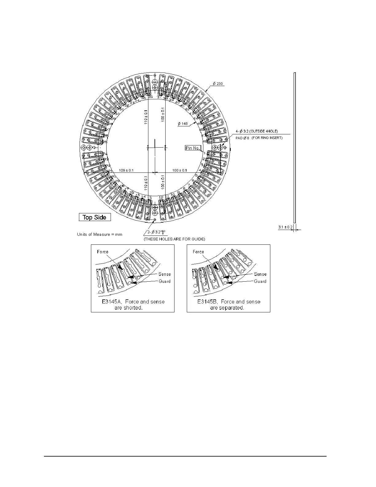
Figure 3-11 E3145A/B personality board dimensions
Extension cable fixture
An extension cable fixture and connector plate are used to interface between the testhead measurement pins and the
probe needles. Agilent Technologies provides the Agilent E3146A extension cable fixture for the 4072A/B tester.
The E3146A is designed so that all the measurement pins of the testhead contact the pads of this fixture, and can be
wired to the connector plate or to the probing needles easily. For details, see theE3146A Operation Guide.
Wiring for extension cable fixture
The customer is responsible for the wiring between the extension cable fixture and the probe needles. The prober
manufacturer or its representative can help you wire the connector plate or probing needles.
See the pin board configuration table in “Pin board configuration” on page 55 to determine which testhead slots
will have pin boards installed at the factory. Do not reconfigure the pin board locations. The slot numbers in the
table correspond to pin numbers on the extension cable fixture that should be used when connecting to the probe
card.