38 Chapter 2
Agilent 4072/4073 Preinstallation Guide, Edition 4
Site Preparation
Emergency Off (EMO) System
• Turning on system instrument
Switching on the main breaker, the emergency breaker, and the main switch turns on the LINE indicator
(white), but the main contactor switch does not close. Figure 2-18 through Figure 2-20 show this condition.
When the system switch closes, power is supplied to the system controller. When the EMO panel
INSTRUMENT POWER ON switch closes, the coil of the main contactor is activated and the main contactor
switch closes. The INSTRUMENT POWER ON indicator (green) also turns on. Power is then supplied to the
system instruments.
• Turning off system instrument
Pressing the EMO panel INSTRUMENT POWER OFF switch stops the current through the coil of the main
contactor, so the main contactor opens. This stops power to the system instruments.
• EMO switch
When the EMO switch is pressed and its contacts open, the current through the coil of the main contactor stops
and the main contactor opens. The emergency breaker contacts also open. This stops power to both the system
instruments and system controller.
At the same time, the current through the coil of Relay2 flows, so one contact opens and the other contact
closes in Relay2. The Ext alarm 1, which is normally in the closed state, is opened, and the Ext alarm 2, which
is normally in the open state, is closed.
Opening the Ext control terminal is the same as pressing the EMO switch, which stops current through the coil
of Relay2, so one contact opens and the other closes. The current through the coil of the main contactor then
stops, the main contactor opens, and power to the system instruments stops. This also stops power to the system
controller.
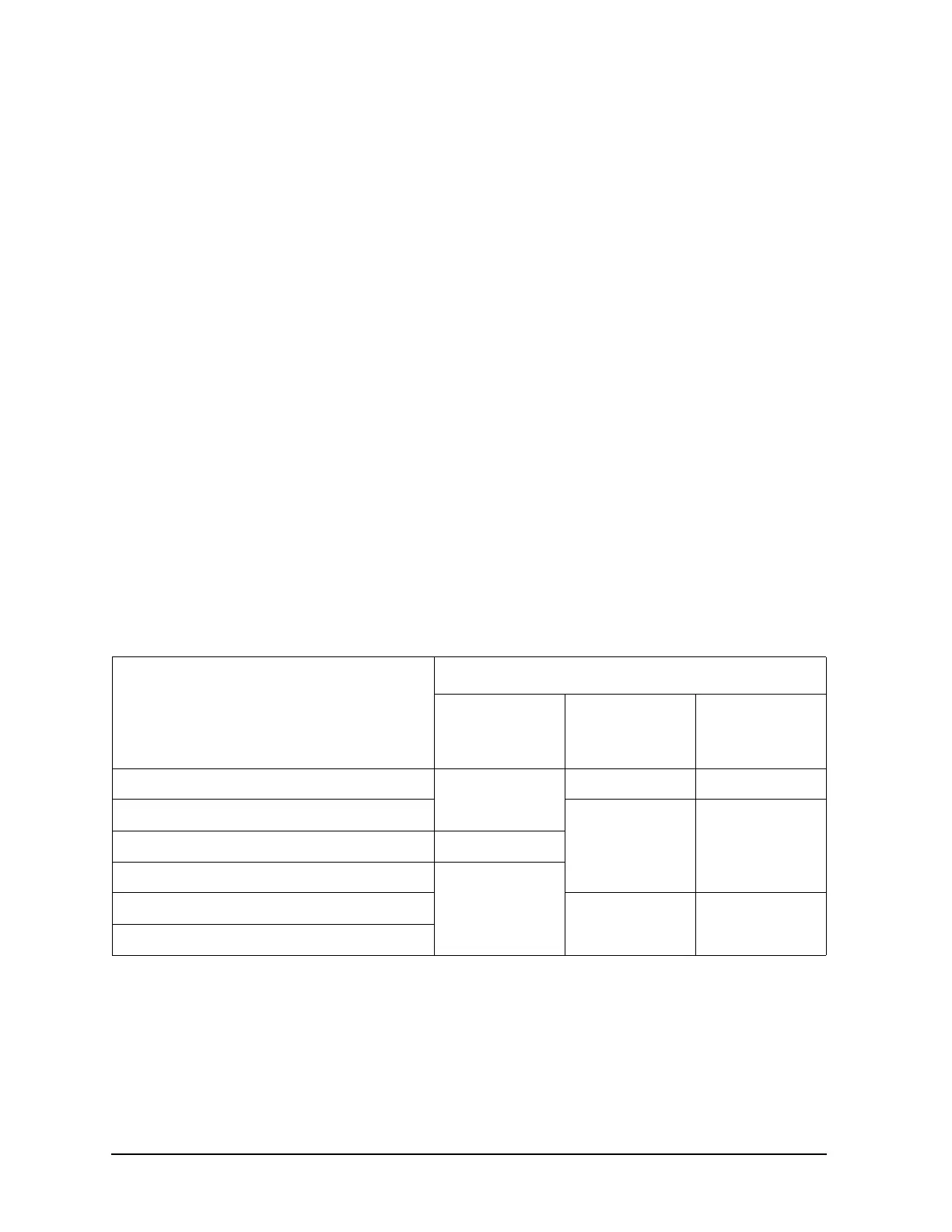
Table 2-6 describes conditions for normal operation.
Table 2-6 Conditions for normal operation
Operation
Results
Power for
system
instruments
Ext. alarm 1
(NC)
a
a. NC (“Normally Closed”) indicates that the terminals are closed when the tester operates properly.
Ext. alarm 2
(NO)
b
b. NO (“Normally Open”) indicates that the terminals are open when the tester operates properly.
Disconnect device is ON
not supply
Open Close
Pressing system switch
Close OpenPressing INSTRUMENT POWER ON switch supply
pressing INSTRUMENT POWER OFF switch
StopPressing EMO switch
Open Close
Opening Ext. control