Installation
20 Agilent 5800 and 5900 ICP-OES User's Guide
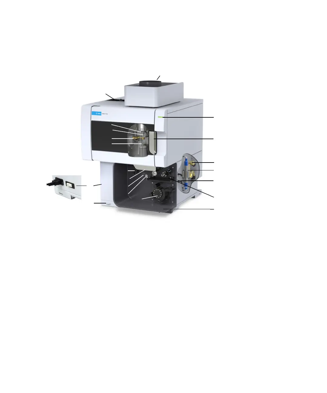
Agilent ICP-OES Instrument Overview
Figure 1. Front and side of the ICP-OES instrument
1. Exhaust 8. Torch loader handle 15. Torch compartment handle
2. Air inlet filter 9. Spray chamber 16. Water inlet assembly
3. Pre-optics cone and axial
viewing window (not shown)
10. Nebulizer 17. Optics purge filter for argon or
nitrogen
4. Snout and radial viewing
window (not shown)
11. Peristaltic pump 18. Gas supply assembly
5. Work coil 12. Mains power switch and
cable connection
19. Optional AVS 4, AVS 6 or AVS 7
Switching Valve accessory location
6. Torch 13. Front panel power button 20. Drain for liquid overflow
7. Nebulizer and make up gas
connections
14. LED instrument status
indicator
11
7
9
10
8
1
14
2
5
3
18
15
16
17
6
13
12
20
4
19