7.
YO
Driv
er
Gain
and
Linearity
Description
and Procedure
No test
equipment
is
required
for
these
adjustmen
ts.
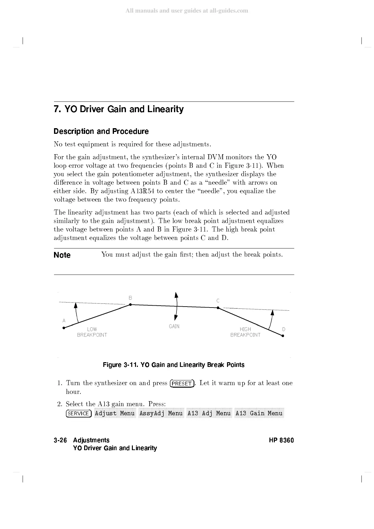
F
or the
gain
adjustmen
t,
the
syn
thesizer's
in
ternal
D
VM
monitors
the
YO
lo
op
error
v
oltage
at
t
w
o
frequencies
(p
oin
ts
Band
Cin
Figure 3-11
).
When
y
ou
select
the
gain p
otentiometer
adjustmen
t,
the
syn
thesizer
displa
ys
the
dierence
in
voltage
b
et
w
een
p
oin
ts
B
and
C
as
a
\needle"
with
arro
ws
on
either
side.
By
adjusting
A13R54
to
cen
ter
the
\needle",
y
ou
equalize
the
v
oltage b
et
w
een
the
t
w
o
frequency
p
oin
ts.
The
linearit
y
adjustmen
t
has
t
w
o
parts
(eac
h
of
whic
h
is
selected
and
adjusted
similarly
to
the
gain
adjustment).
The lo
w
break
p
oin
t
adjustmen
t
equalizes
the
v
oltage
b
et
w
een
p
oin
ts
A
and B
in Figure
3-11
.
The
high
break
p
oin
t
adjustmen
t
equalizes
the
v
oltage
b
et
w
een
p
oin
ts
C
and
D.
Note
Y
ou
m
ust
adjust
the
gain
rst;
then
adjust
the break
p
oin
ts.
Figure
3-11. YO Gain and Linearity Break P
oints
1. T
urn the syn
thesizer on and press
4
PRESET
5
. Let it w
arm up for at
least one
hour.
2. Select the A13 gain men
u. Press:
4
SERVICE
5
NNNNNNNNNNNNNNNNNNNNNNNNN
NNNNNNNNNN
Adjust Menu
NNNNNNNNNNNNNNNNNNNNNNNNN
NNNNNNNNNNNNN
AssyAdj Menu
NNNNNNNNNNNNNNNNNNNNNNNNN
NNNNNNNNNNNNN
A13 Adj
Menu
NNNNNNNNNNNNNNNNNNNNNNNNN
NNNNNNNNNNNNNNNN
A13 Gain
Menu
3-26 Adjustments
YO Driver Gain and Linearity
HP 8360