EasyManuals Logo

Agilent Technologies 83620A User Manual

Agilent Technologies 83620A
687 pages
To Next Page IconTo Next Page
To Previous Page IconTo Previous Page
Page #638 background imageLoading...
Page #638 background image
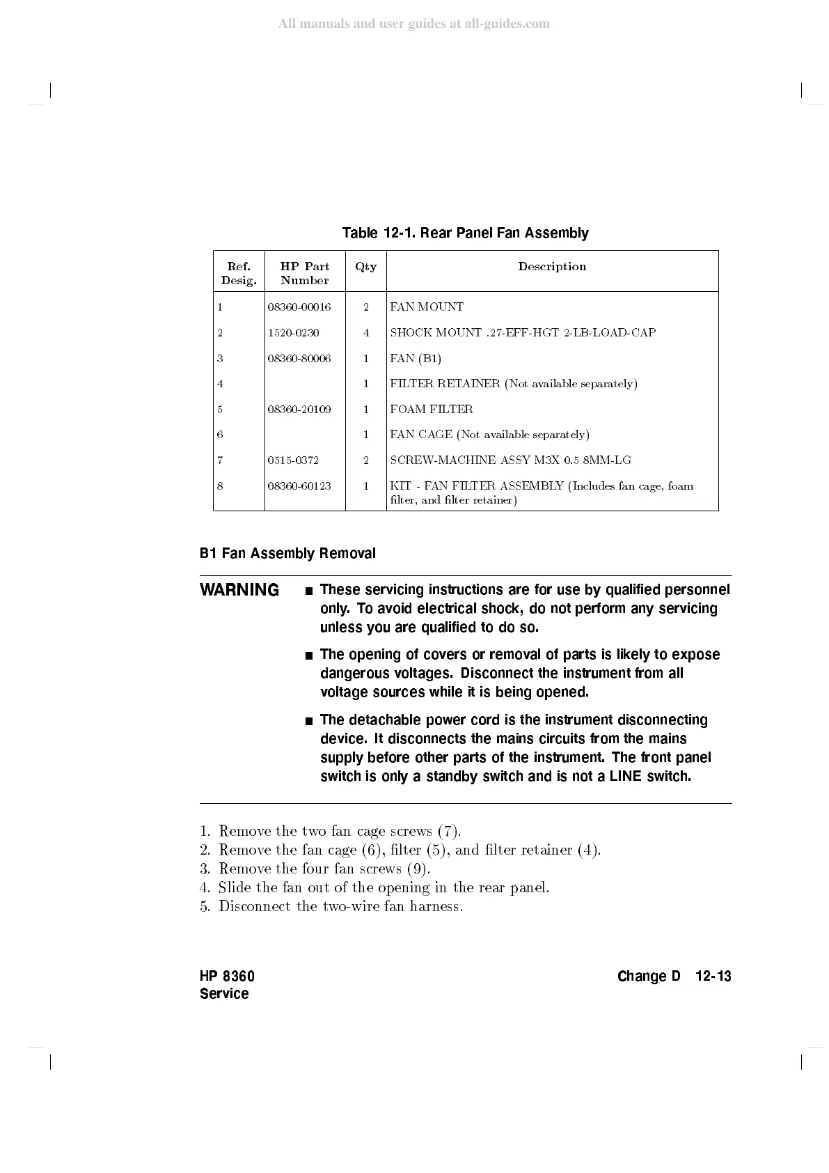
Table
12-1.
Rear
P
anel
F
an
Assembly
Ref.
Desig.
HP
P
art
Num
b
er
Qt
y
Description
1 08360-00016 2 F
AN
MOUNT
2 1520-0230 4 SHOCK
MOUNT
.27-EFF-HGT
2-LB-LOAD-CAP
3 08360-80006 1 F
AN (B1)
4 1 FIL
TER
RET
AINER
(Not
a
v
ailable
separately)
5 08360-20109 1 F
O
AM
FIL
TER
6 1 F
AN
CA
GE
(Not
a
v
ailable
separately)
7 0515-0372 2 SCREW-MA
CHINE
ASSY
M3X
0.5 8MM-LG
8 08360-60123 1 KIT
-
F
AN
FIL
TER
ASSEMBL
Y
(Includes
fan
cage,
foam
lter,
and
lter
retainer)
B1
F
an
Assembly
Remov
al
W
ARNING
These
servicing
instructions
are
for
use
b
y
qualified
personnel
only
.T
oa
v
oid
electrical
shock,
do
not
perform
any
servicing
unless
y
ou
are
qualified
to
do
so.
The
opening
of
co
v
ers
or
remov
al of
parts
is
lik
ely
to
expose
dangerous
v
oltages.
Disconnect
the
instrument
from
all
voltage
sources while
it
is
being
opened.
The
detachable
po
wer
cord is
the instrument
disconnecting
device.
It
disconnects
the
mains
circuits
from
the
mains
supply before
other parts
of
the
instrument.
The
front
panel
switch
is
only
a
standb
y
switch
and
is
not
a LINE
switch.
1. Remo
ve the t
wo fan cage
screws (7).
2. Remove the fan cage (6), lter (5), and lter retainer (4).
3. Remo
ve the four fan screws (9).
4. Slide the fan
out of the opening in the rear panel.
5. Disconnect the t
wo-wire fan harness.
HP 8360
Service
Change D 12-13
All manuals and user guides at all-guides.com

Table of Contents

Questions and Answers:

Question and Answer IconNeed help?

Do you have a question about the Agilent Technologies 83620A and is the answer not in the manual?

Agilent Technologies 83620A Specifications

General IconGeneral
BrandAgilent Technologies
Model83620A
CategoryBlower
LanguageEnglish