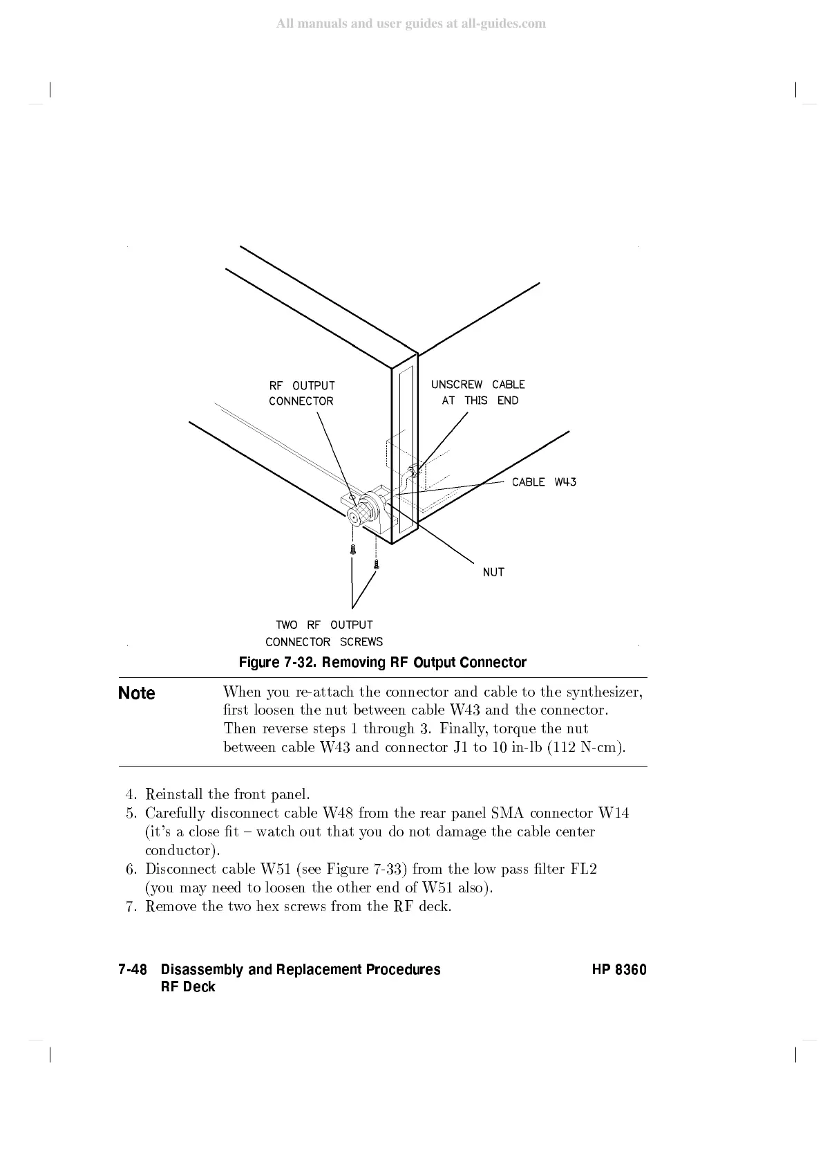
Figure
7-32.
Remo
ving
RF
Output
Connector
Note
When
y
ou
re-attac
h
the
connector
and
cable
to
the
syn
thesizer,
rst
lo
osen
the
n
ut
b
et
w
een
cable
W43
and
the
connector.
Then rev
erse steps
1 through
3.
Finally
,
torque
the
n
ut
b
et
w
een
cable
W43
and
connector J1
to 10
in-lb (112
N-cm).
4. Reinstall the fron
t panel.
5. Carefully disconnect cable W48 from the rear
panel SMA connector W14
(it's a close t { w
atch out that y
ou do not damage the cable cen
ter
conductor).
6. Disconnect cable
W51 (see Figure 7-33) from the lo
w pass lter FL2
(you ma
y need to lo osen the other end of W51 also).
7. Remo
ve the t
w
o hex screws from the RF dec
k.
7-48 Disassembly and Replacement Procedures
RF Deck
HP 8360