5 Configure the display and the measurement:
Press [
Display
], [
2grids
], [
more display setup
], [
grids off
].
Press [
B
], [
Measurement Data
], [
main time
] (toggle to ch1 on a 2-channel analyzer).
Press [
Ref Lvl/Scale
], [
Yperdiv
], 50, [
mV
].
Press [
Trigger
], [
trigger type
], [
internal source
].
Press [
Time
], [
main length
], 32, [
us
].
6 Set up the time gating and examine the first burst:
Press [
Time
], [
gate on
], [
gate length
], 10, [
us
].
Press [
ch1 gate dly
], [
Marker|Entry
]
Rotate the knob until the gate is at each end of the first burst signal.
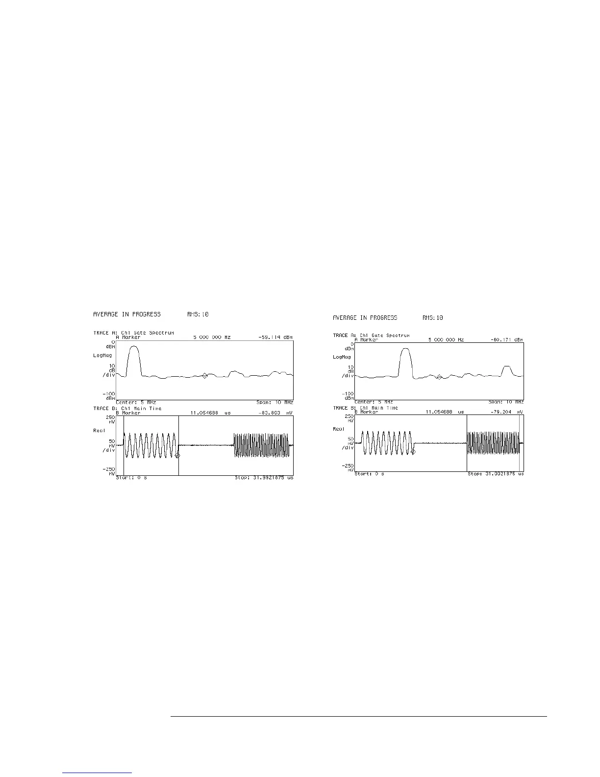
The display should now appear as shown to the left below.
7 Examine the second burst:
Rotate the knob until the gate is at each end of the second burst signal.
The display should now appear as shown to the right below.
Note that the [
Time
] menu must be displayed, the [
gate delay
] softkey active, and
the knob in the Entry mode to move the gate by turning the knob.
Spectrum (top trace) of the burst is derived by gating the time signal (bottom trace).
The gate’s delay and length are selected to encompass the burst signal (vertical
markers show gate position). Note existence of the first spectral component in
the left display and the existence of the other two components in the right display.
Using Gating to Characterize a Burst Signal
3-3

 Loading...


