Signal Generator Overview
Front Panel
Chapter 1 5
Front Panel
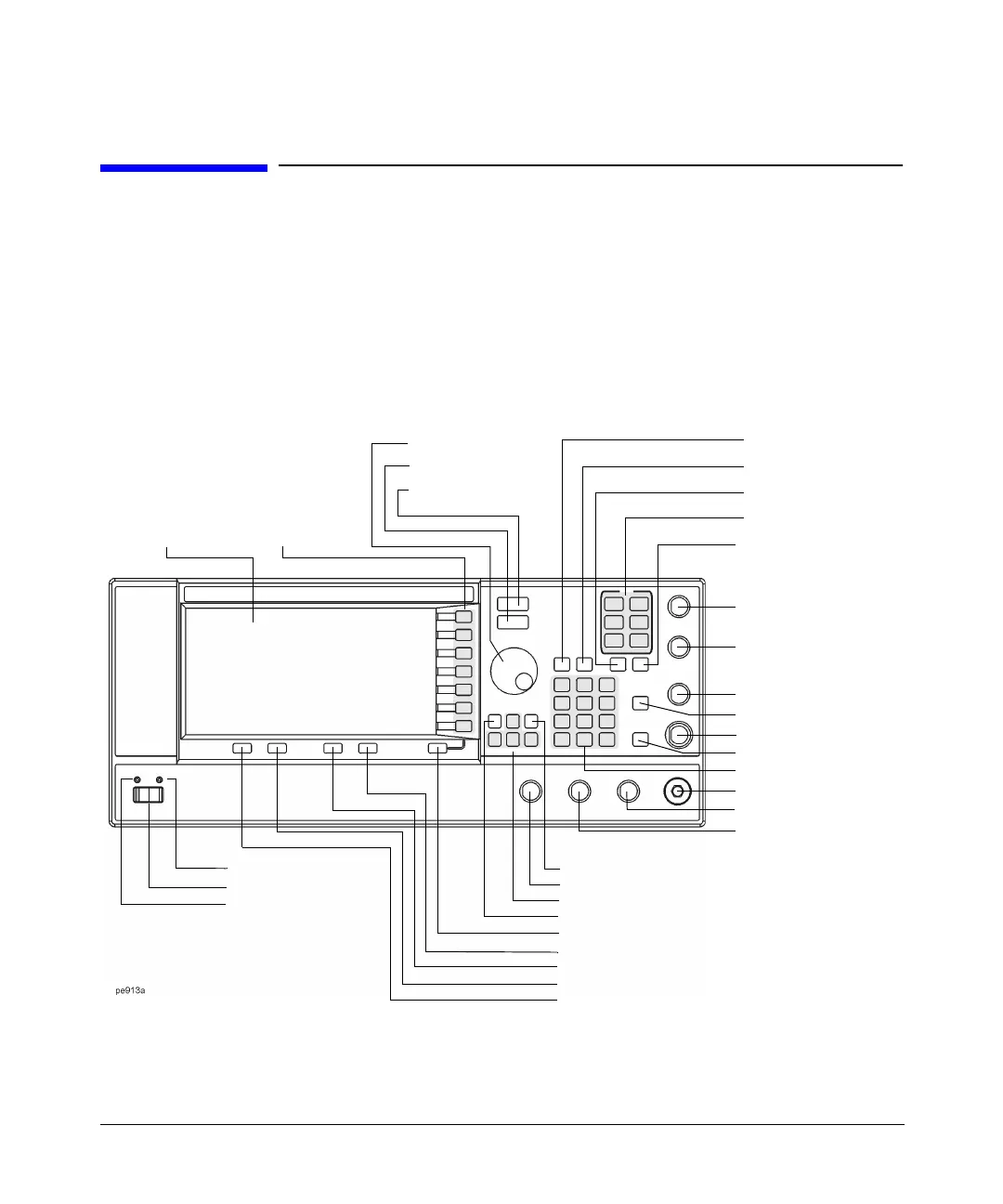
Figure 1-1 shows the PSG-A signal generator front panel. This interface enables you to define,
monitor, and manage input and output characteristics. Although Figure 1-1 shows the PSG-A
Series front panel, descriptions are valid for both PSG Series.
The PSG-L Series front panel has fewer connectors and menu hardkeys. Connector
descriptions that do not apply to the PSG-L Series front panel are specified as “PSG-A only”.
Figure 1-1 Front Panel Diagram (PSG-A Series shown)
11. EXT 1 INPUT
12. EXT 2 INPUT
10. Help
8. Trigger Key
13. LF OUTPUT
15. ALC INPUT
1. Display
27. Hold
2. Softkeys
3. Knob
4. Amplitude Key
5. Frequency Key
6. Save Key
9. Menu Keys
24. Incr Set Key
7. Recall Key
18. RF OUTPUT
17. Numeric Keypad
26. Arrow Keys
28. Return Key
29. Display Contrast Decrease Key
30. Display Contrast Increase Key
31. Local Key
23. Standby LED
32. Preset Key
22. Power Switch
14. Mod On/Off
16. RF On/Off
21. Line Power LED
19. PULSE SYNC OUT
20. PULSE VIDEO OUT
25. PULSE/TRIGGER GATE INPUT

 Loading...


