Signal Generator Overview
Rear Panel
Chapter 1 15
Rear Panel
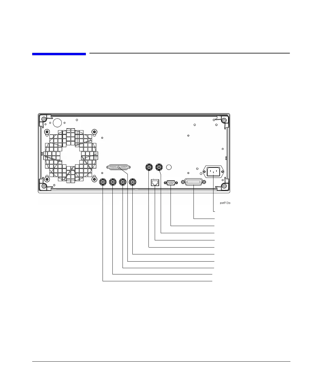
Figure 1-3 shows the signal generator rear panel. The signal generator rear panel provides
input, output, and remote interface connections. Descriptions are provided for each
characteristic of the rear panel.
Figure 1-3 Rear Panel Diagram
1. AC Power Receptacle
The line voltage is connected here. The power cord receptacle accepts a three-pronged power
cable that is shipped with the signal generator.
2. GPIB
The GPIB interface allows listen and talk capability with compatible IEEE 488.2 devices.
3. AUXILIARY INTERFACE
2. GPIB
7. SWEEP OUT
9. TRIGGER OUT
4. 10 MHz IN
6. 10 MHz OUT
10. TRIGGER IN
8. SOURCE MODULE
11. SOURCE SETTLED OUTPUT
5. LAN
1. AC Power Receptacle

 Loading...


