1-43
Troubleshooting
Troubleshooting Assembly–Level Problems
704 Filter Test
1. Refer to Table1-13, and check J1 on the A6 Frac–N:
a. Turn the signal generator on and remove the A6 Frac–N.
b. Set the signal generator to the first center frequency.
c. Use an extender board cable to connect a spectrum analyzer to J1.
d. Tune the spectrum analyzer to the first J1 frequency, and check for the correct power.
e. Repeat Step d for the remaining frequencies.
•If all the signals at J1 are good, continue with Step 3.
2. If any signal measured in Step 1 is bad, check the signal out of the A6 Frac–N output port on the
A29 20 GHz Doubler.
• If the signal out the A29 20 GHz Doubler is good, replace the cable.
• If the signal out the A29 20 GHz Doubler is bad, replace the A29 20 GHz Doubler.
3. If all of the signals at J1 are good, turn the signal generator off and reinstall the A6 Frac–N.
4. Check J4 at the A8 Output (shown on on page 1-62):
a. Power the signal generator on and remove the A8 Output.
b. Use an extender cable to connect a spectrum analyzer to J4.
c. Tune the spectrum analyzer to the first frequency in column one of Table1-13, and check for
approximately +10 dBm.
• If an RF signal is present on J4, replace the A8 Output.
• If an RF signal is not present on J4, replace the A6 Frac–N.
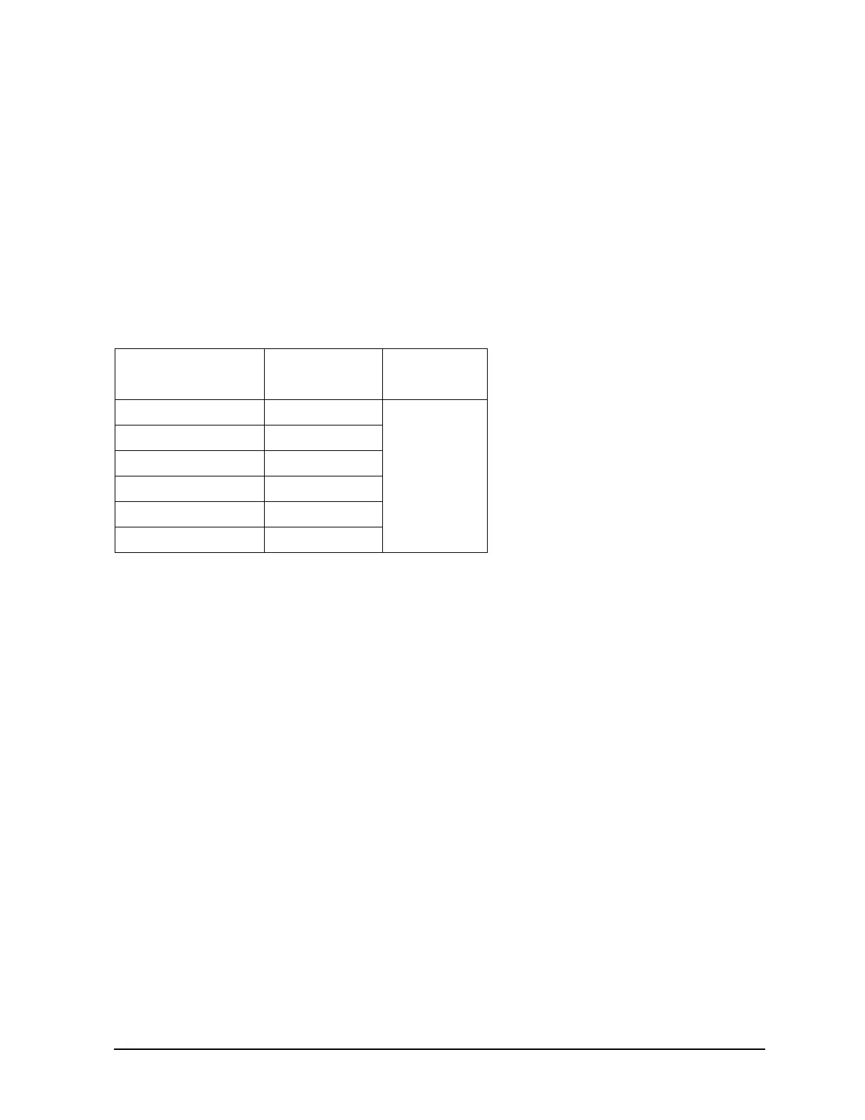
Table 1-13
Center Frequency
(GHz)
J1 Frequency
(GHz)
Power at J1
(dBm)
0.300 4.771
> –6
0.500 7.969
0.750 5.971
1.25 4.976
2.0 7.969
3.0 5.971