Service Appendix D
Series N6700 User’s Guide 175
Step 7. To reinstall the front panel assembly, perform the above steps in
reverse order.
Removing/Installing the Bulk Supply
Step 1. Remove the modules from the mainframe as previously described.
Step 2. Remove the blower cover, bulk supply cover, and interface cover.
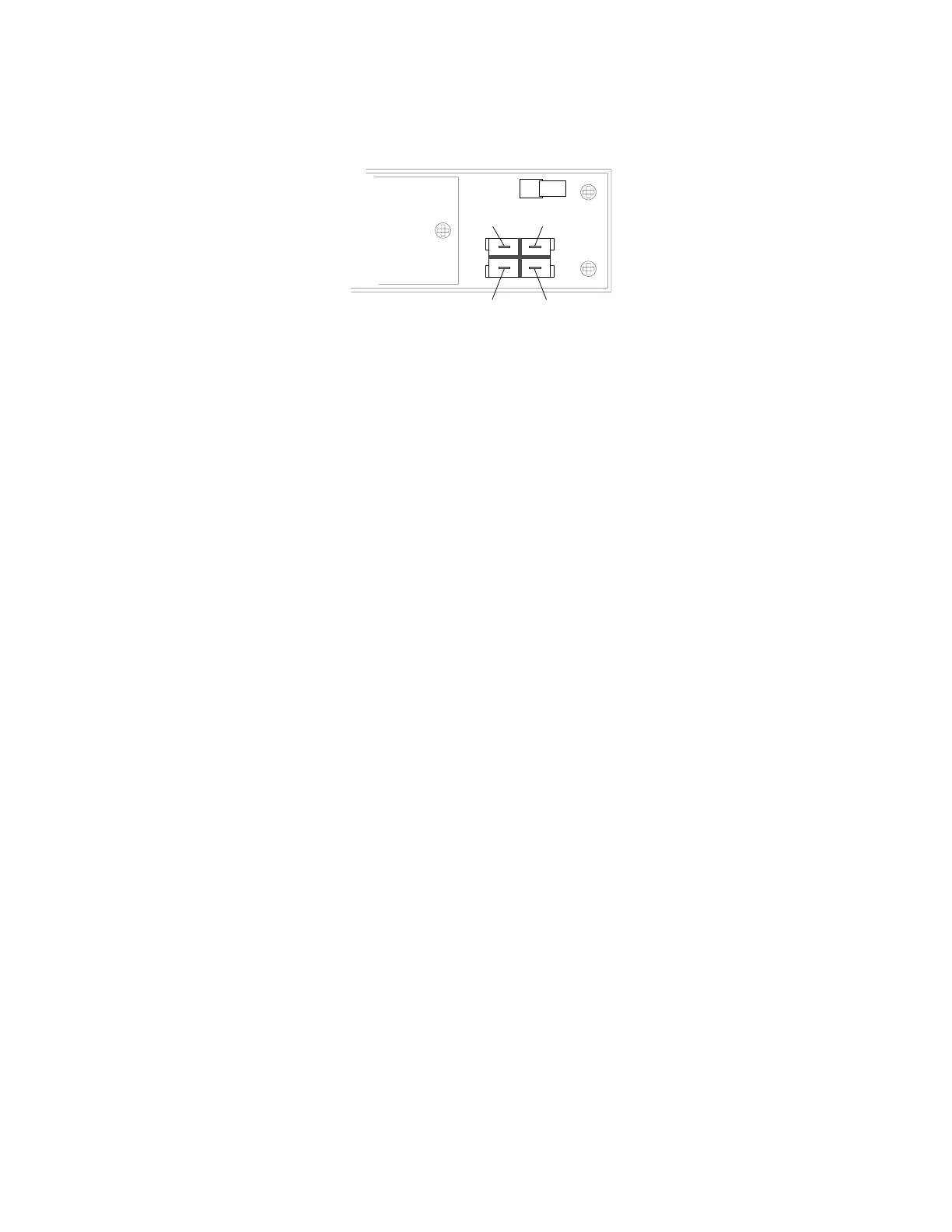
supply to the chassis. Disconnect the DC and AC cable assemblies.
Lift the supply out of the unit.
Step 7. To reinstall the bulk supply, perform the above steps in reverse
order.
Installing a Redundant Ground for 400 Hz Operation
Operation at 400 Hz requires the installation of a redundant ground
from the instrument chassis to earth ground. The redundant ground
must be permanently attached to the unit as well as to the earth
ground point.
The following procedure only describes how to make the permanent
connection at the unit. The user must ensure the integrity and
permanence of the connection at the earth ground point.
The following customer-supplied hardware is required:
Ground wire (14/16 AWG)
Uninsulated ring terminal for attaching wire to unit
Tyco p/n 34122 or equivalent for N6700A mainframes
Tyco p/n 34124 or equivalent for N6700B mainframes
Hardware for attaching wire to earth ground point
The following tools are required for installing the redundant
ground:
5/16 inch hex wrench for N6700A mainframes
3/8 inch hex wrench for N6700B mainframes
Grey White/Brown/Grey
White/GreyWhite/Red
Step 3. Remove the four screws that attach the front panel assembly. Slide
Use a T20 driver and remove the four screws that fasten the bulk
the front panel assembly forward and away from the chassis.
Step 4. You now have access to the four screws that install the bulk supply.
 Loading...