2 Installation
20 Series N6700 User’s Guide
400 Hz Operating Considerations
Power Factor
At 400 Hz operation, the unit’s power factor is affected as follows:
Under full load at 400 Hz, power factor drops from 0.99 (@120
VAC) to as low as 0.76 (@ 265 VAC)
Power factor degrades further under no load conditions.
Redundant Ground Requirement
At 400 Hz operation, the leakage current of the unit exceeds 3.5 mA.
This requires the installation of a permanent, redundant ground from
the instrument chassis to earth ground. This ensures that ground will
always be connected and that any leakage current will be diverted to
ground. Appendix D describes how to connect the redundant ground.
Connecting the Outputs
WARNING
SHOCK HAZARD Turn off AC power before making rear panel connections.
All wires and straps must be properly connected with the terminal block
screws securely tightened.
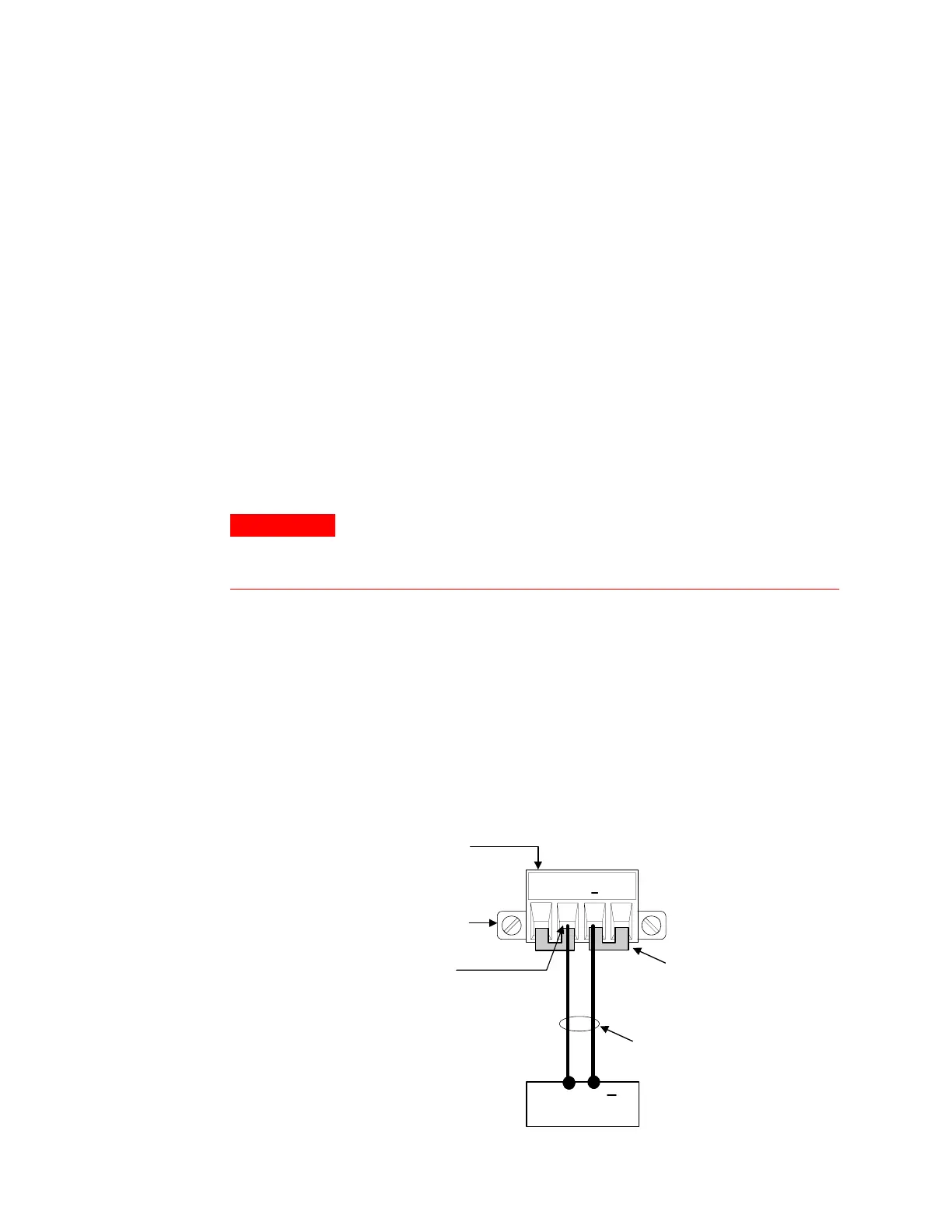
Disconnect the connector plug to make your wire connections. The
connector accepts wires sizes from AWG 12 to AWG 30. Note that
wire sizes smaller than AWG 20 are not recommended. Each
connector has four openings for attaching wires (see the figure
below). Load connections are made at the + and - terminals. Sense
connections are made on the +s and -s terminals. Securely fasten the
wires by tightening the screw terminals.
After your wires are securely connected, insert the connector plug
into the back of the unit and secure it by tightening the locking
screws. A chassis ground binding post is available next to the AC
input connector for your convenience.
+S + -S
LOAD
TWIST LEADS
+
CONNECTOR
PLUG SHOWN
INSERT WIRES
TIGHTEN SCREWS
LOCKING SCREW
SENSE JUMPERS
INSTALLED FOR
LOCAL SENSING
 Loading...