Appendix D Service
176 Series N6700 User’s Guide
Step 1. Remove the top cover of the GPIB board as previously described in
this appendix under “Accessing the Calibration switch”.
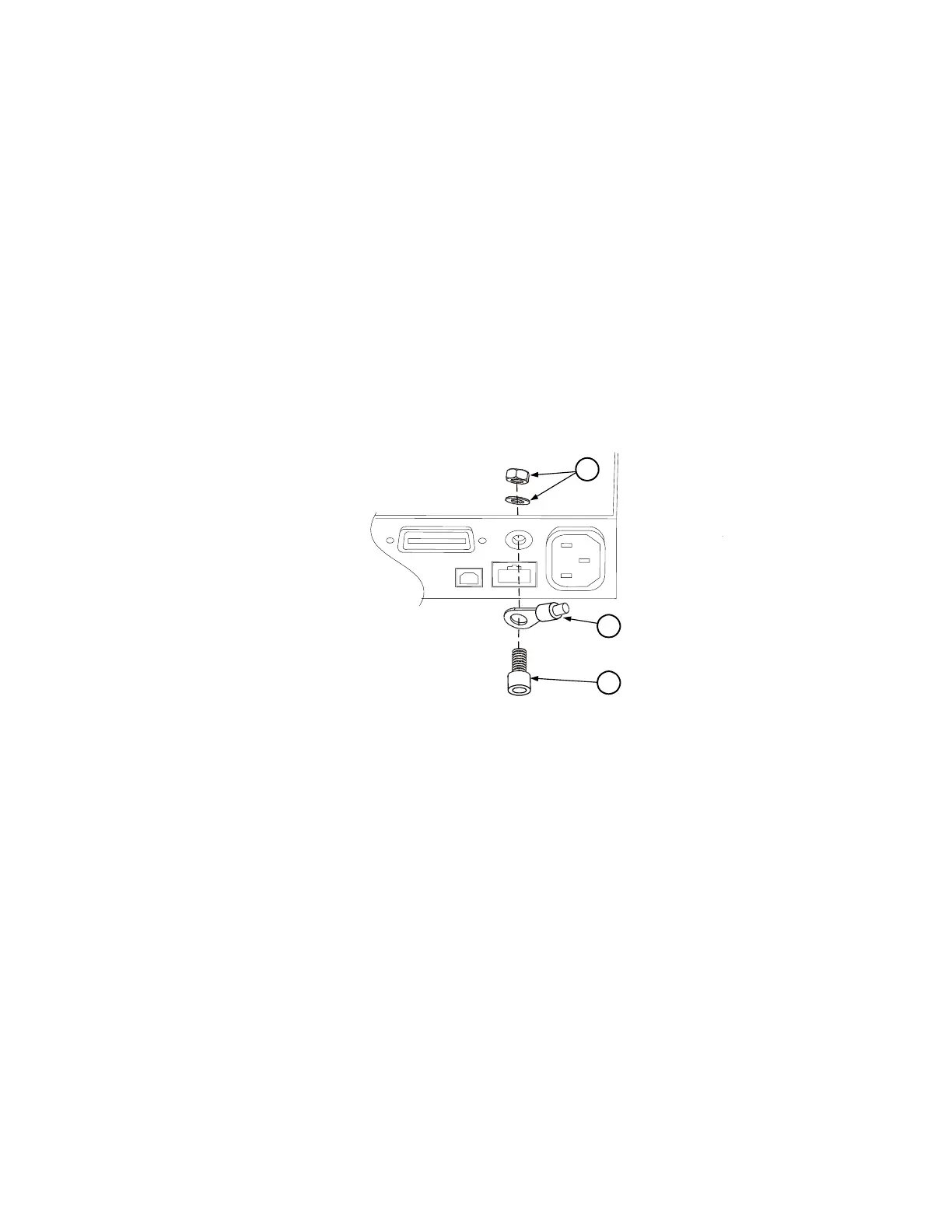
Step 2. Use the wrench and remove the binding post (1) from the rear of the
chassis. The binding post is located between the AC input connector
and the GPIB connector.
Step 3. Crimp the appropriate ring terminal (2) onto the end of the ground
wire.
Step 4. Place the ring terminal onto the threaded end of the binding post. Re-
install the binding post on the chassis with the washer and nut (3).
Step 5. Rotate the ring terminal so that the ground wire does not interfere
with any other connectors on the back of the unit. Use the wrench
and tighten the binding post to the chassis.
Torque for N6700A mainframes = 15 – 20 in-lb.
Torque for N6700B mainframes = 20 – 25 in-lb.
Troubleshooting
Before performing the Overall Troubleshooting procedures, perform
the Operating Checkout procedure in the beginning of this chapter.
If the power system passes selftest and there are no obvious faults,
perform the verification procedures in Appendix B to determine if
any power modules are not calibrated, or are not operating properly.
This will help isolate a problem to a specific power module.
1
2
3
 Loading...