Installation 2
Series N6700 User’s Guide 25
Parallel Connections
CAUTION
Only connect outputs that have identical voltage and current ratings in parallel.
Connecting outputs in parallel provides a greater current capability
than can be obtained from a single output.
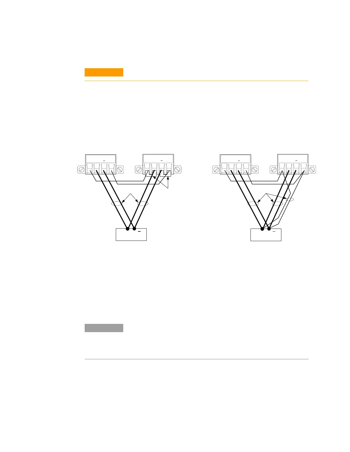
The following figures show how to connect two outputs in parallel.
The figure on the left illustrates local sensing. If voltage drop in the
load leads is a concern, the figure on the right shows how to connect
the sense leads directly at the load. Note that in both cases, the
remote sense terminals must be connected together.
Grouping the Outputs
Once outputs have been connected in parallel, they can be configured
or “grouped” to act as a single, higher-power channel. This applies
when programming via the front panel or using SCPI commands.
Information about how to group output channels that have been
connected in parallel is provided in Chapter 4 under “System Related
Operations” as well as Chapter 6 under ”System Commands”.
NOTE
The ability to group outputs is only available on Agilent N6700 MPS mainframes
with firmware revision B.00.00 and up. Almost all instrument functionality is
supported by grouped channels, including voltage and current programming,
measurements, status, step transients, and list transients.
To program paralleled outputs on units with earlier version
firmware, first program both outputs to the desired output voltage.
Then program the current limit point of each output. The current
limit of the paralleled outputs will be the sum of both individual
current limit points.
OUTPUT 2 OUTPUT 1
+S + -S
LOAD
+S + -S
WITH LOCAL SENSING
+
OUTPUT 1
+S + -S
OUTPUT 2
+S + -S
WITH REMOTE SENSING
TWIST LEADS
LOAD
+
SENSE
JUMPERS
INSTALLED
TWIST LEADS
 Loading...