Appendix D Service
180 Series N6700 User’s Guide
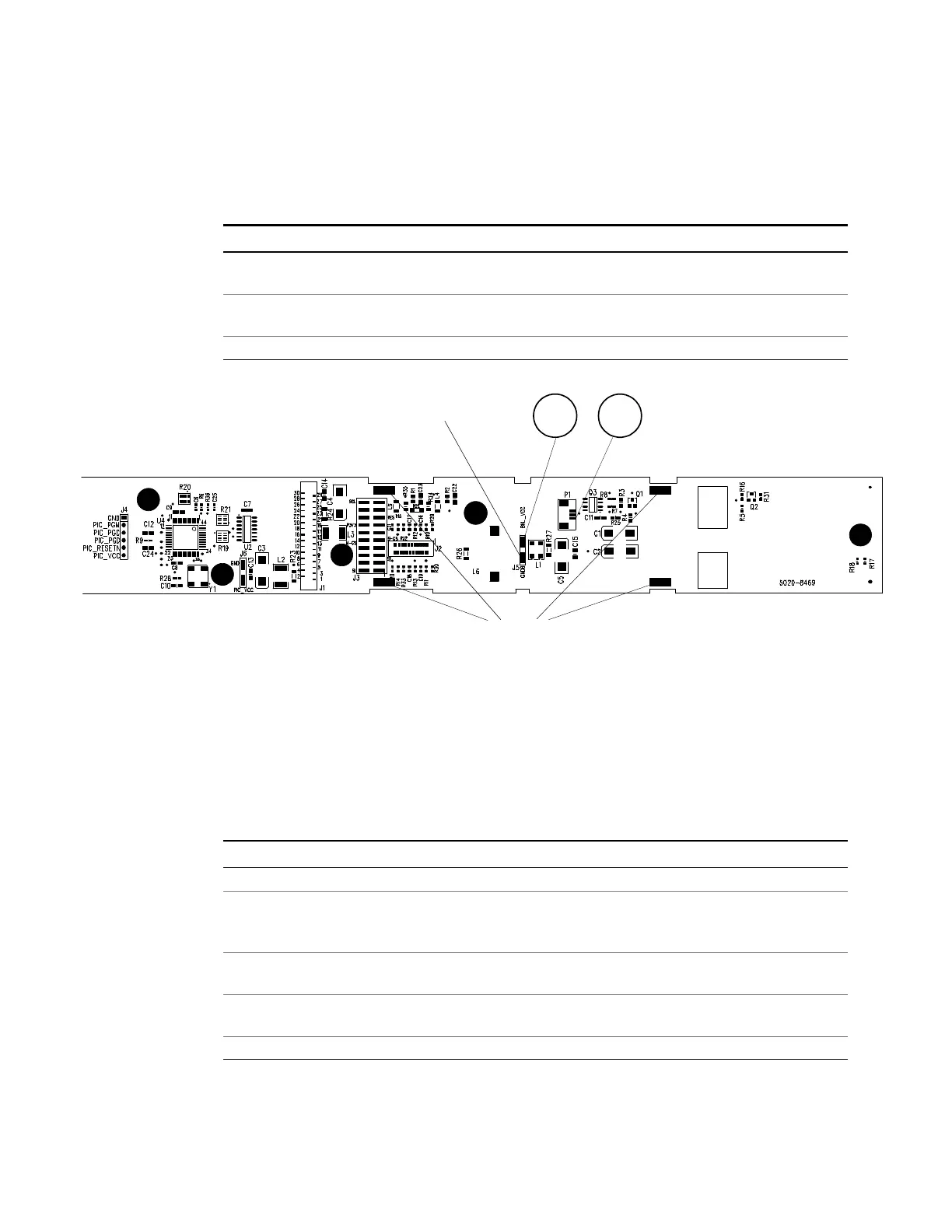
Front Panel Troubleshooting
Troubleshooting the front panel board involves checking for the
presence of the correct bias voltages on the board. Refer to the
following table and figure.
Test Point Location Voltage Action
TP 1 BKL_VCC +12 V If bias not present, troubleshoot the carrier/bias board or replace
the front panel board.
TP 2 P1 pin 3 +12 V If backlight voltage not present, replace the front panel board.
If voltage is present and the display is not lit, replace the display.
Common GNDB Common
Carrier/Bias Board Troubleshooting
Troubleshooting the carrier board involves checking for the correct
bias voltages on the board. Refer to the following table and figures.
Note that if the bias voltages at test points 2 - 4 in the following table
are not present, it could be caused by a defect in the power module
or interface board that is pulling the bias voltage low.
Test Point Location Voltage Action
TP 1 + RED +48 V Output of bulk supply. If not present, replace the bulk supply.
TP 2 + C4 +12 V If biases at TP 2, TP 3, or TP 4 are not present, disconnect the
backplane and interface board and recheck again (see note 1).
If biases are still not present, replace the carrier/bias board.
TP 3 U9 - 2 (N6700B)
U10 - 8 (N6700A)
+5 V Same as above.
TP 4 + C3 (N6700B)
U5 - 2 (N6700A)
+3.3 V Same as above.
Common − BLK Common
NOTE 1
On N6700B mainframes, disconnect cable #15. (Refer to parts location diagrams.)
On N6700A mainframes, disconnect cables #12 and #13. Unplug the interface board from
the carrier board.
2
1
COMMON
TABS
 Loading...