36 Installation Note E4440-90613
Installation Procedure
CAUTION In the following step use a 7 mm wrench on the end of W46 to avoid
stressing this cable. The cable can be damaged if it is allowed to rotate
when loosening or tightening the Attenuator connector.
30.Locate 0955-0246 3 dB Attenuator from the kit. Connect 3 dB Attenuator to W46 as
shown. Torque to 10 in-lbs.
CAUTION In the following step, use a 5/16 inch wrench on the wrench flat at the
end of the attenuator to prevent the attenuator body from rotating
when installing Cable W98. This attenuator and cable can be damaged
if the attenuator is allowed to rotate when loosening or tightening the
cable connector.
31.Locate E4446-20074 semi-rigid cable from the kit. (Preselector Bypass Mixer to 3 dB
Attenuator / Cable W46 / A12 FELOMA) This cable is reference designator W98.
Connect one end of W98 to the 3 dB Attenuator and the other end to the Preselector
Bypass Mixer. Torque to 10 in-lbs.
32.Connect Cable W93 (Coaxial Switch Port 2 to Preselector Bypass Mixer) Torque to
10 in-lbs.
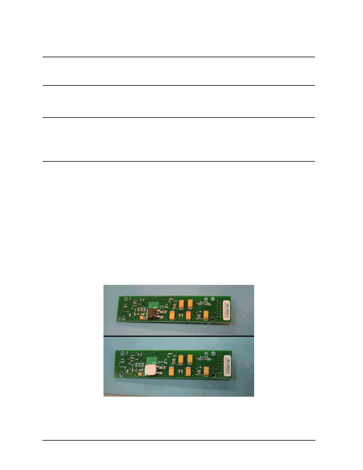
33.Locate Mixer Bias Board A35 (E4440-60254) and Thermal Pad (N1996-40018) from
the kit. Use a pair of tweezers to carefully peel the clear protective cover from the
pink side of the Thermal Pad. Refer to Figure 29. Apply the pink side of the Thermal
Pad to the voltage regulator on the Mixer Bias Board. (The voltage regulator is the
square black component near the center of the board). Peel the blue protective cover
off of the Thermal Pad.
Figure 29 Mixer Bias Board

 Loading...


